11 · Ready-wired projects
Example projects
Every bundled example as its own guide: the circuit preview, the parts on the bench, the code, and a one-click link that opens it live in the simulator.
Each card below is a complete, working project. The page shows the exact circuit the simulator renders, the code it runs, and every part on the bench; the button on each page opens it live so you can probe, edit, and break it. In the app, the same gallery lives behind Examples in the header: browse by section, search, or filter by hardware (ESP32, Wi-Fi, displays, sensors), and look for the badges: ★ featured, ▶ runs a MicroPython script on boot, ⚙ ships an Arduino C++ sketch.
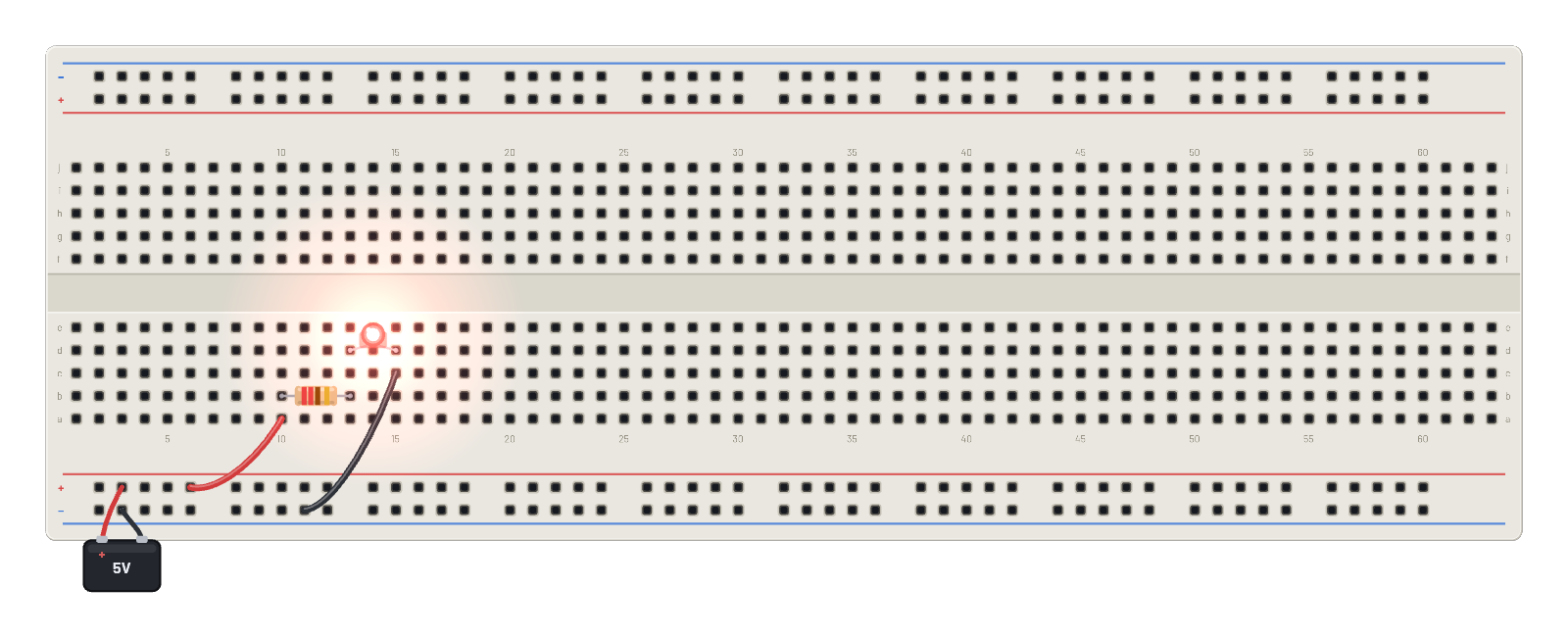 My first circuitBattery → resistor → LED. The hello-world of breadboards.
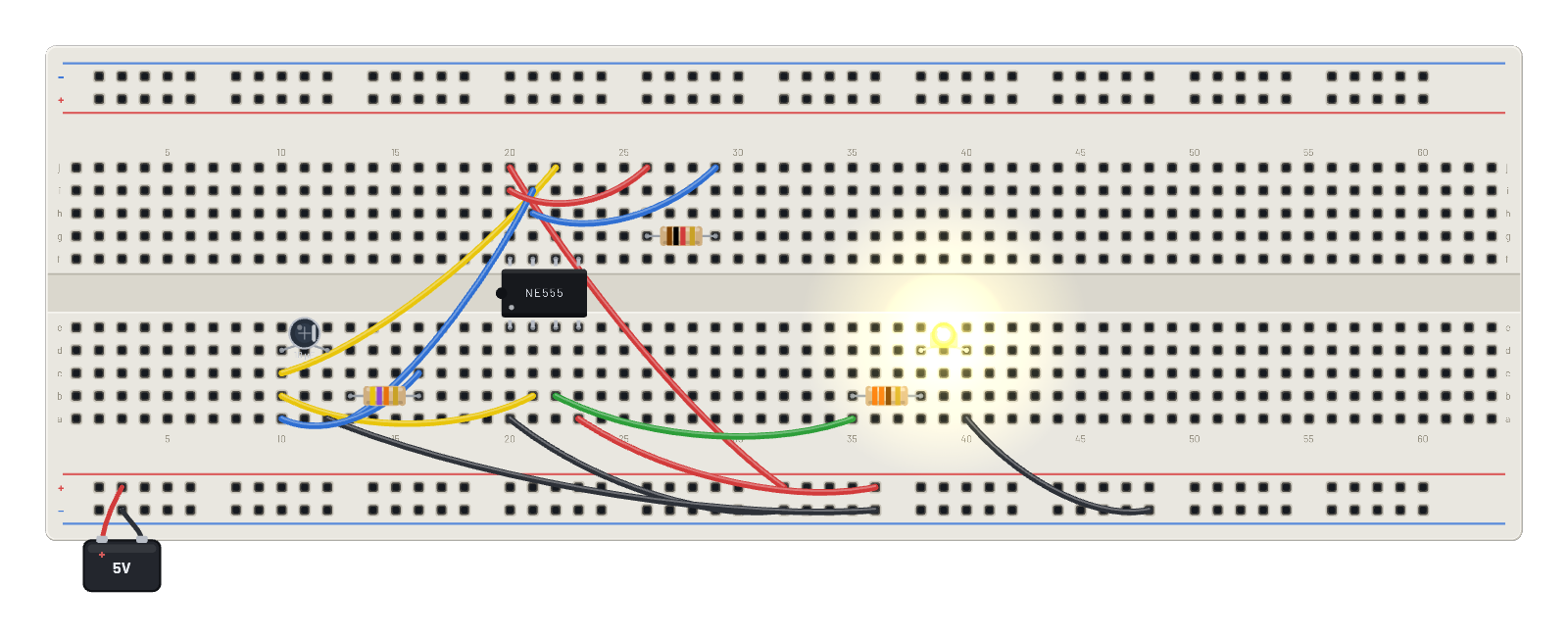 555 LED flasherThe classic NE555 astable blinking an LED at ~1.5 Hz. Probe the cap to watch it ramp.
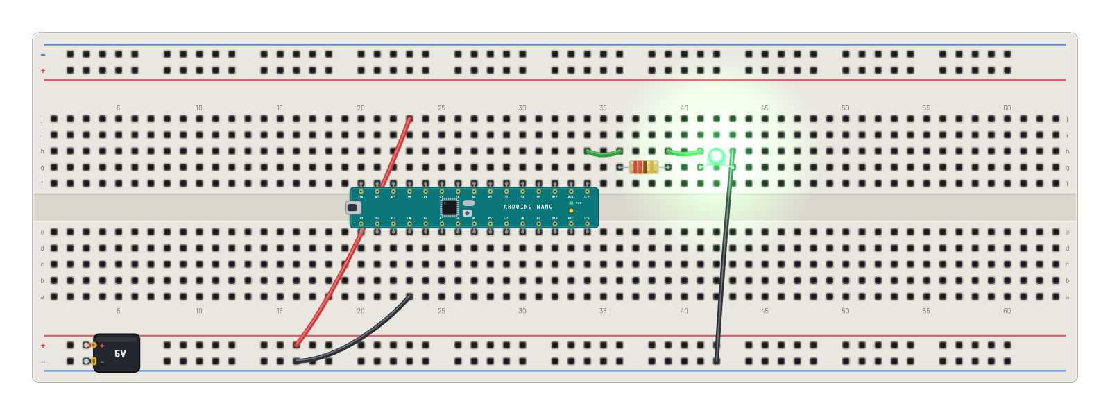 Nano blinkA real Arduino Nano running real AVR machine code, toggling D13 every 0.5 s — the board’s own "L" lamp and the LED on the bench follow the same pin. The Code tab holds the matching editable Arduino sketch; sign in and press Compile & upload to build and flash your own.
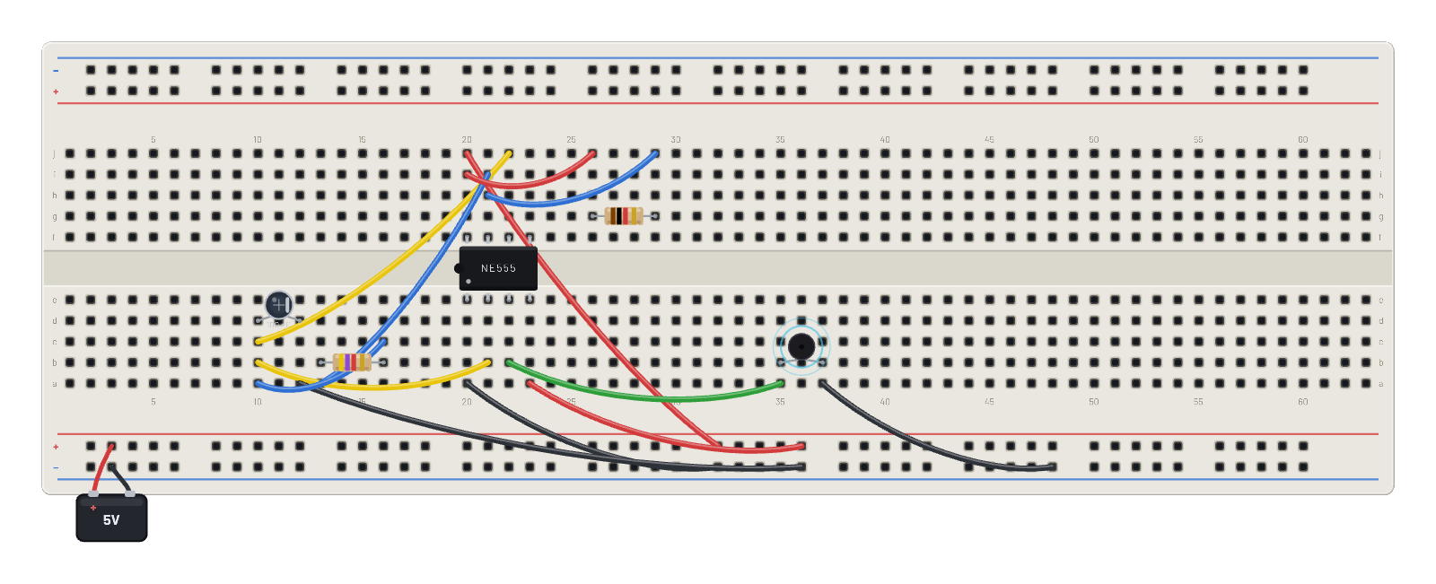 555 tone generatorThe astable at ~1.4 kHz drives a piezo buzzer. Click 🔊 in the header to actually hear it; change C or Rb to change the pitch.
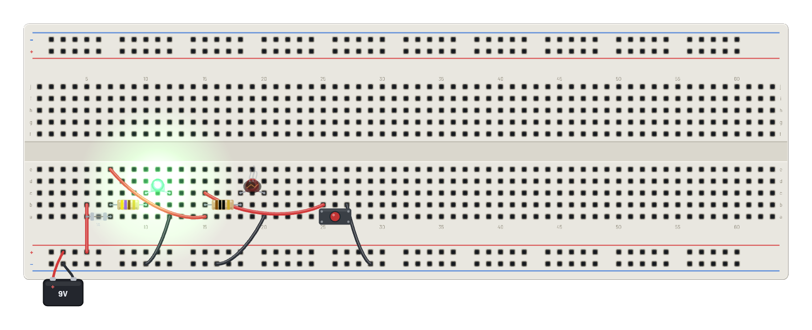 Burn-out labOne LED wired right, one wired wrong: watch the wrong one cook. Then press the button to short the rail and blow the fuse.
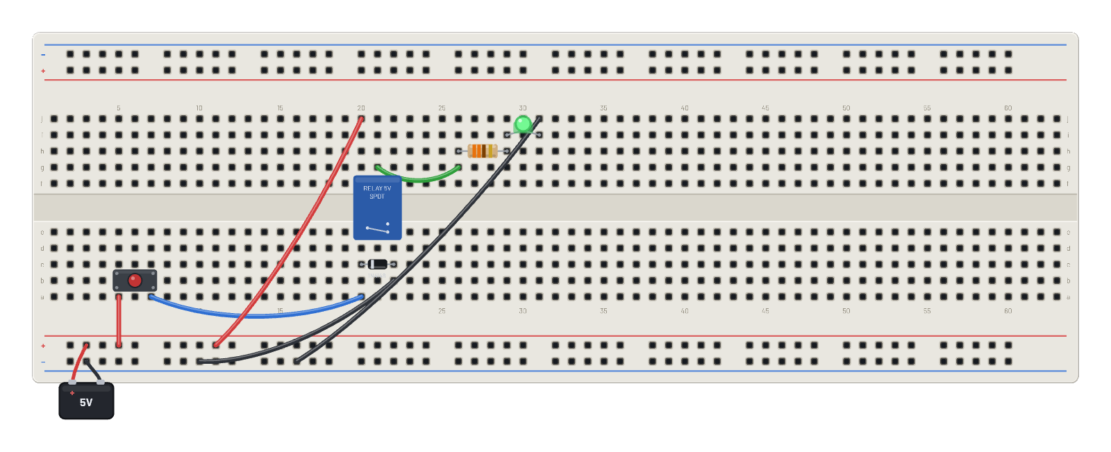 Relay + flyback diodeHold the button to energize the coil; COM swings to NO and lights the LED. The diode across the coil tames the inductive kick.
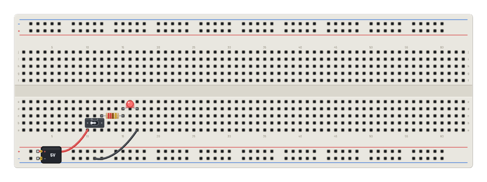 Toggle switch flashlightBattery → toggle switch → resistor → LED. Click the lever to flick it — the contact latches, and the position saves with the circuit.
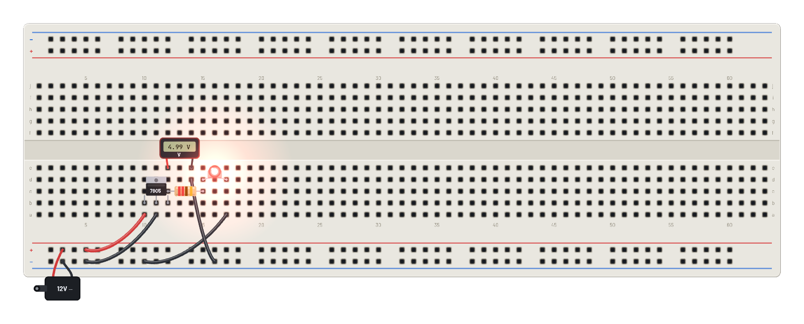 5 V regulated supplyA 7805 turns the 12 V barrel jack into a clean 5 V rail. Watch the voltmeter hold 5 V as you change the input.
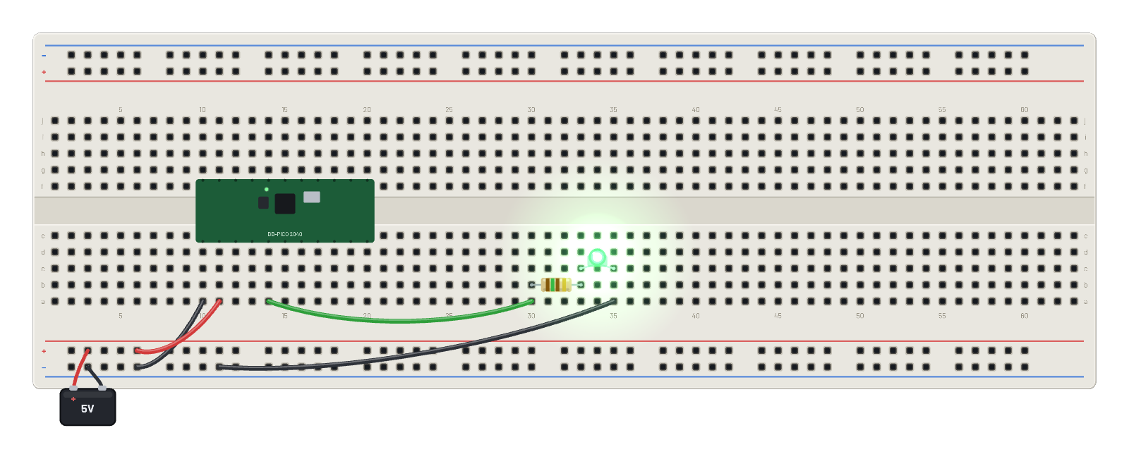 Pi Pico blinkA real emulated RP2040 (Cortex-M0+ at 125 MHz) running bare-metal Thumb assembly: 3.3 V logic blinking an LED on GP2.
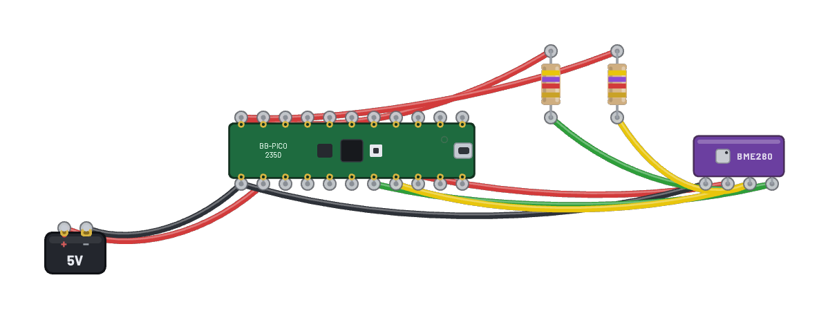 Pico 2 I2C weather stationA real RP2350 boots the pinned official MicroPython v1.29.0 image (the default Arm build, on its Cortex-M33 cores), scans a BME280 and OLED on I2C0 (GP4/GP5), then continuously reads, displays, and prints the live weather values. Both devices use direct machine.I2C operations; change the sensor or disconnect SDA to see the real bus respond.
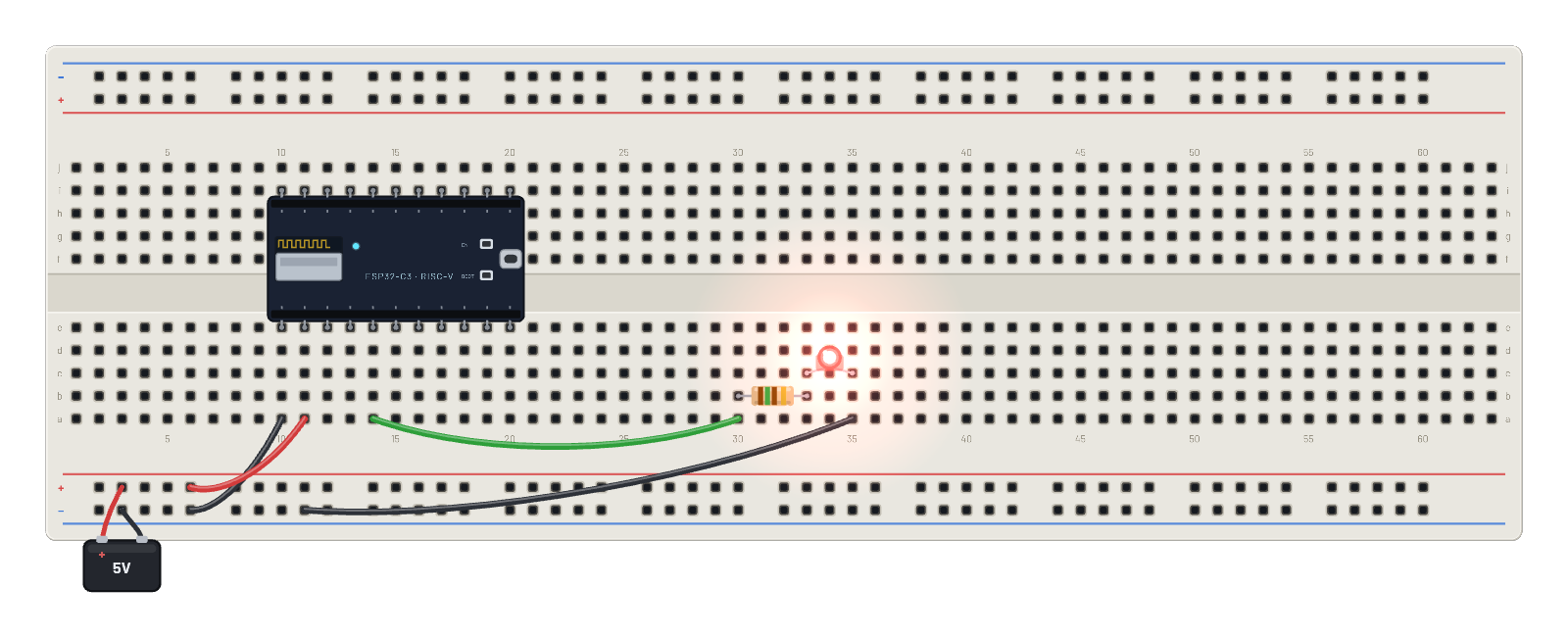 ESP32 blinkA real emulated ESP32-C3 (RISC-V RV32IMC at 160 MHz, Rust→WASM) booting genuine MicroPython and blinking the LED on G2. The blink code lives in the Code tab; edit it and run it again.
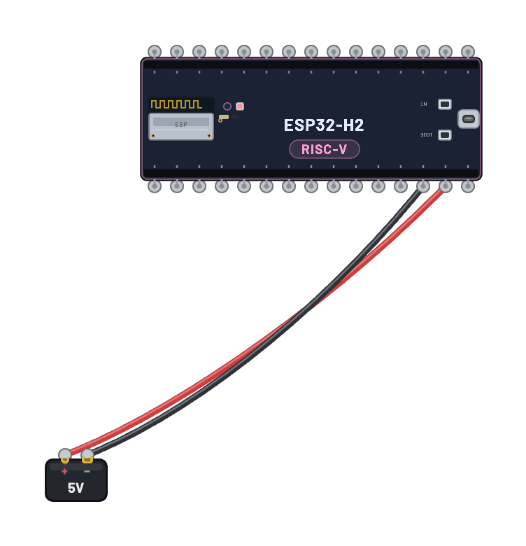 ESP32-H2 blinkA real emulated ESP32-H2 (single RISC-V RV32IMAC at 96 MHz, 320 KB SRAM) runs the bundled chip-specific firmware and blinks its onboard G8 RGB pixel. H2 has Bluetooth LE and 802.15.4 for Thread/Zigbee, but deliberately no Wi-Fi or MicroPython target.
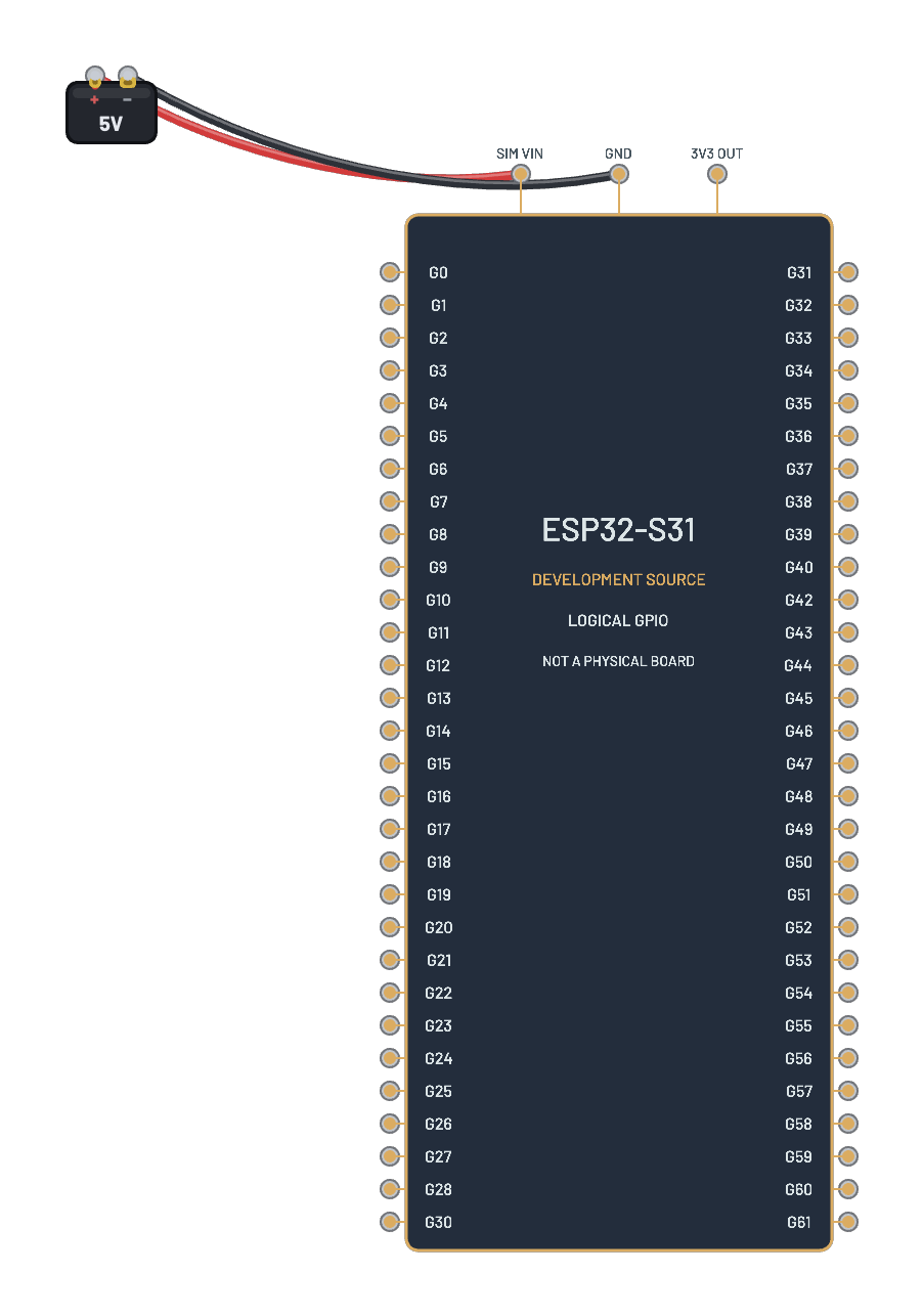 ESP32-S31 development-source helloPinned preview-IDF hello_world on two real emulated HP harts. Open Serial for the countdown and guest restart. Logical GPIO component; bounded development-source support, no radios or physical flashing.
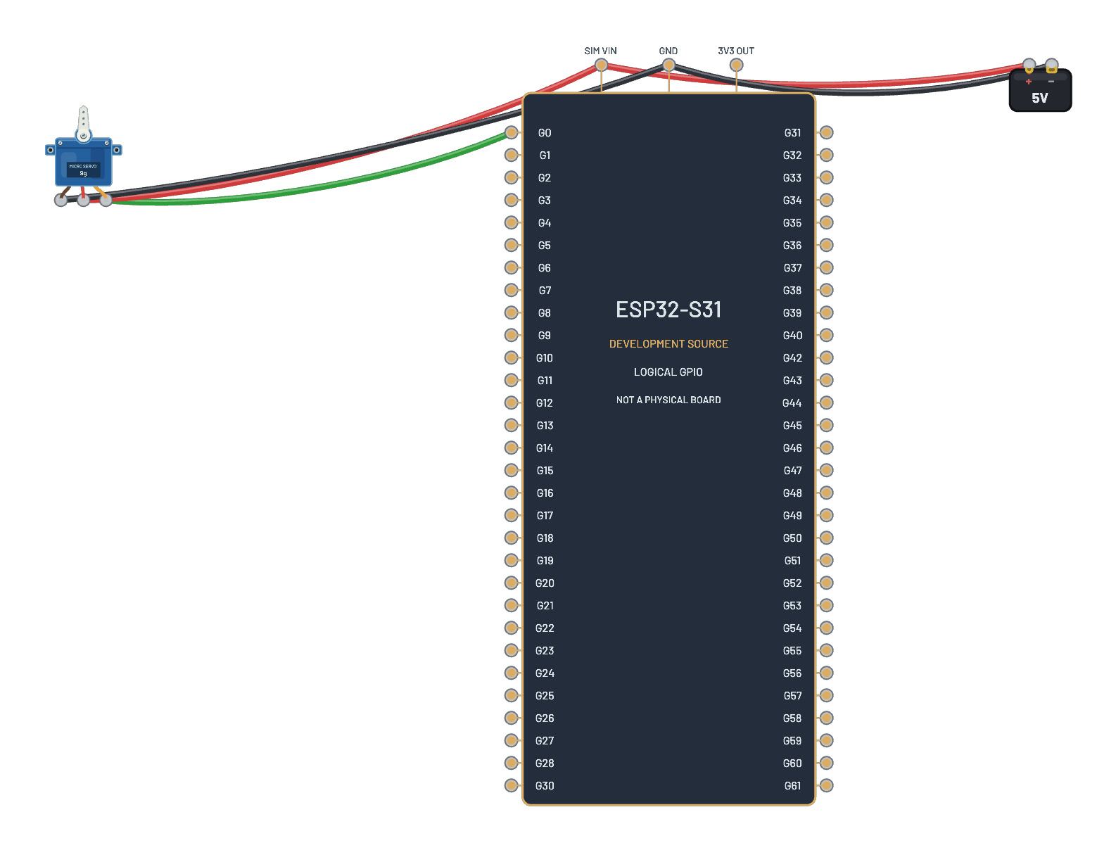 ESP32-S31 servo sweepMCPWM on GPIO0 sweeps the powered servo with 20 ms pulses. Serial reports the programmed angles; the servo maps 1–2 ms pulses to its own 0–180° range. Enable verbose in Serial to see the stock INFO lines. Unmodified pinned ESP-IDF development source on the bounded S31 simulator profile; no physical flashing.
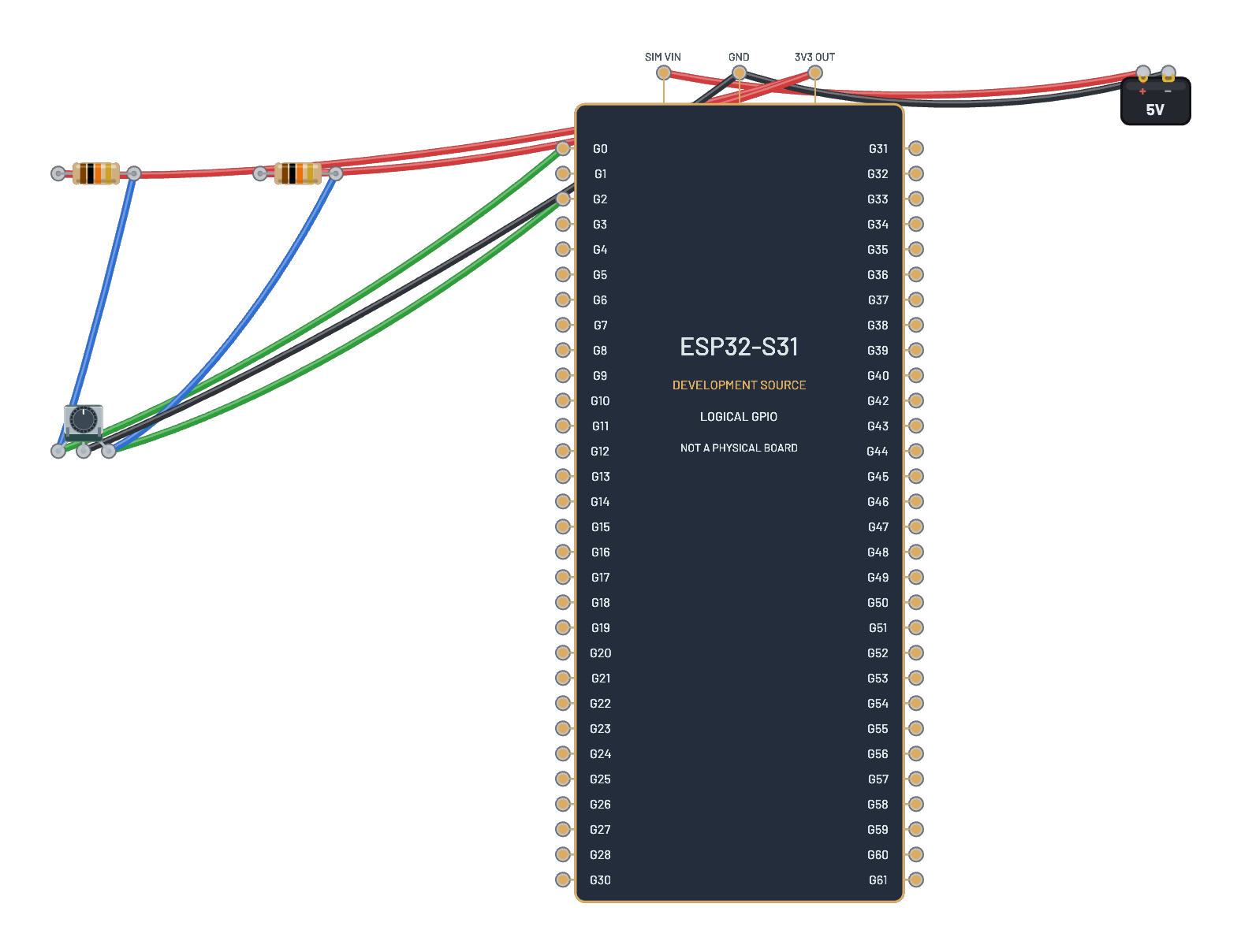 ESP32-S31 rotary encoderTurn the encoder on GPIO0/GPIO2 and watch signed pulse counts in Serial. Two 10 kΩ pull-ups hold its contacts at 3V3; the stock PCNT program resets at ±100. Enable verbose in Serial to see the stock INFO lines. Unmodified pinned ESP-IDF development source on the bounded S31 simulator profile; no physical flashing.
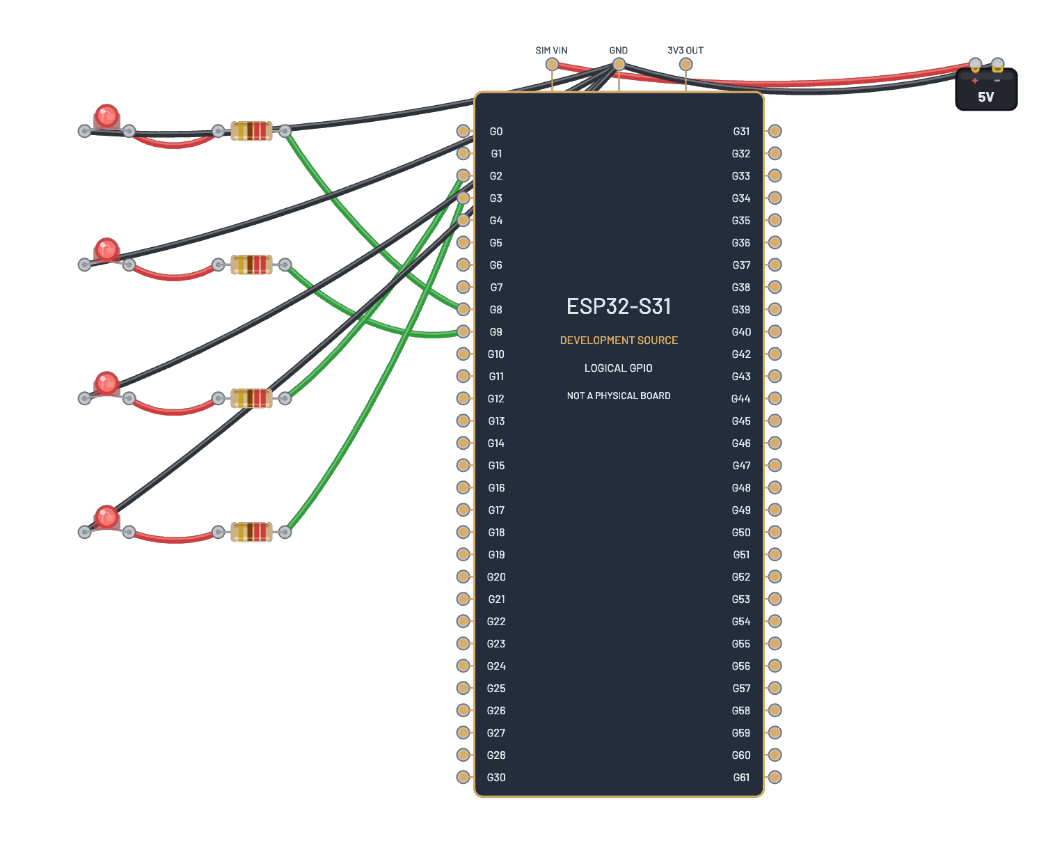 ESP32-S31 four fading LEDsFour 220 Ω LED loads on GPIO8/9/2/3 follow interrupt-rearmed LEDC fades and fixed-duty steps. GPIO2/3 are inverted, so their LEDs fade in the opposite direction. Open Serial for the four phases. Enable verbose in Serial to see the stock INFO lines. Unmodified pinned ESP-IDF development source on the bounded S31 simulator profile; no physical flashing.
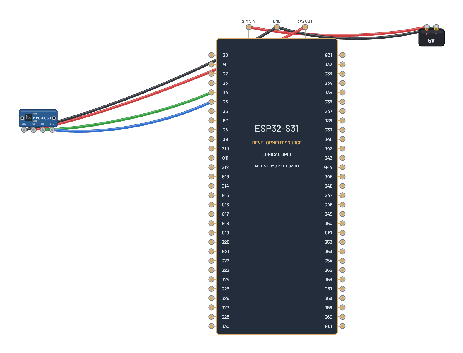 ESP32-S31 MPU-6050 identityThe stock I2C program powers an MPU-6050 from 3V3 and reads its identity at 0x68 on GPIO4 SCL/GPIO5 SDA using internal pull-ups. Serial prints WHO_AM_I = 68, then resets the sensor and returns. Enable verbose in Serial to see the stock INFO lines. Unmodified pinned ESP-IDF development source on the bounded S31 simulator profile; no physical flashing.
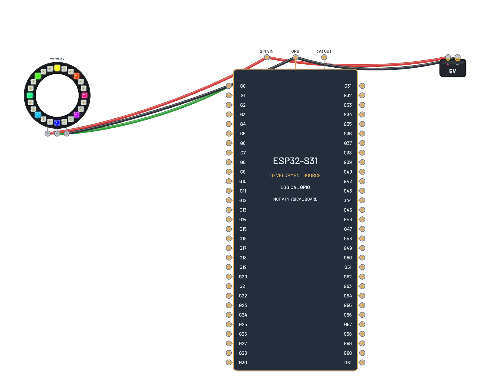 ESP32-S31 rainbow ringRMT on GPIO0 drives a powered 24-pixel ring through the stock rainbow chase. The upstream program's byte order exchanges red and blue on GRB pixels; its source is unchanged. Serial announces the chase. Enable verbose in Serial to see the stock INFO lines. Unmodified pinned ESP-IDF development source on the bounded S31 simulator profile; no physical flashing.
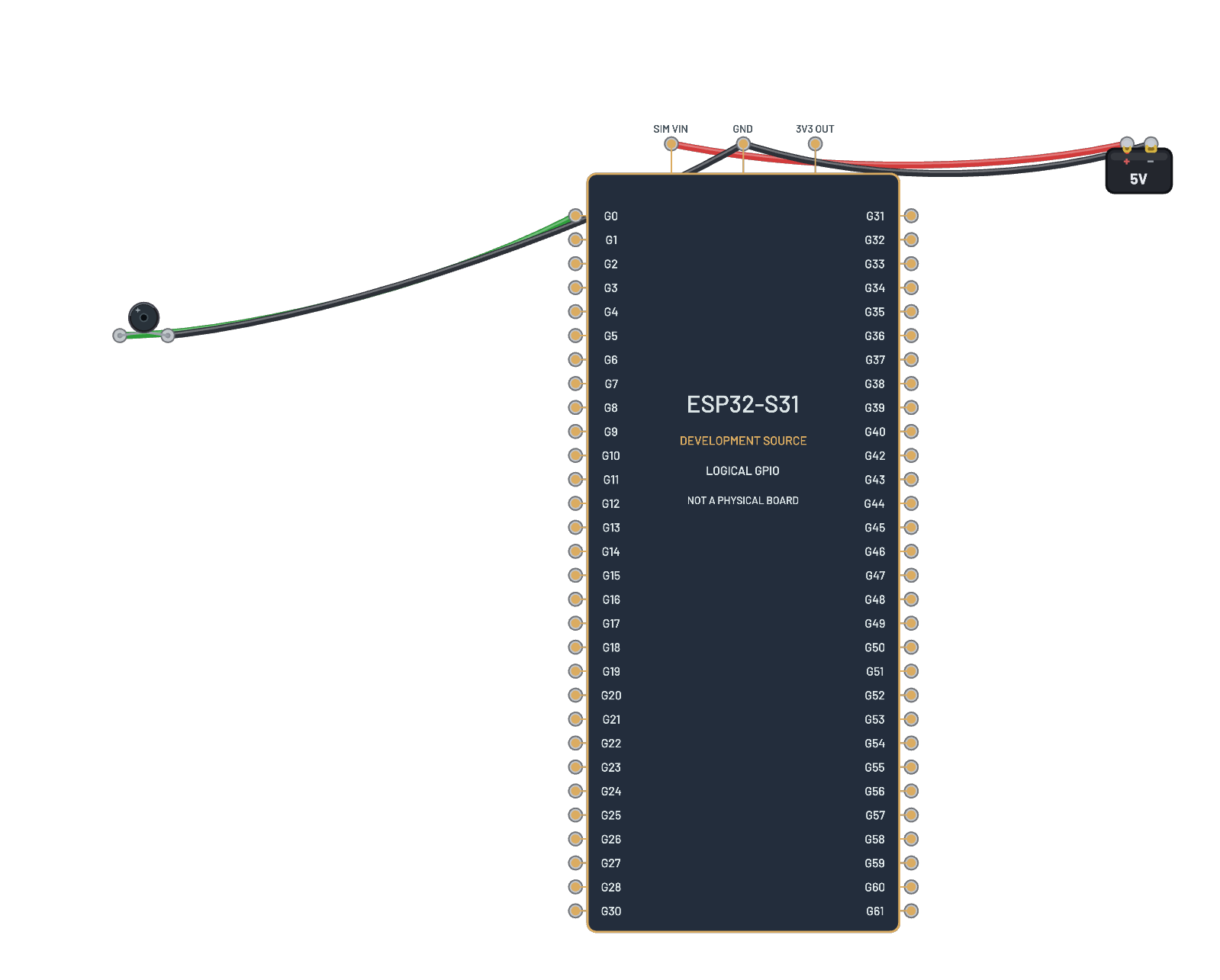 ESP32-S31 Ode to joyRMT on GPIO0 plays the stock Ode to joy score through a passive buzzer. Enable Sound in Settings to listen; pitches and note lengths follow the driver's integer timing. The score plays once. Enable verbose in Serial to see the stock INFO lines. Unmodified pinned ESP-IDF development source on the bounded S31 simulator profile; no physical flashing.
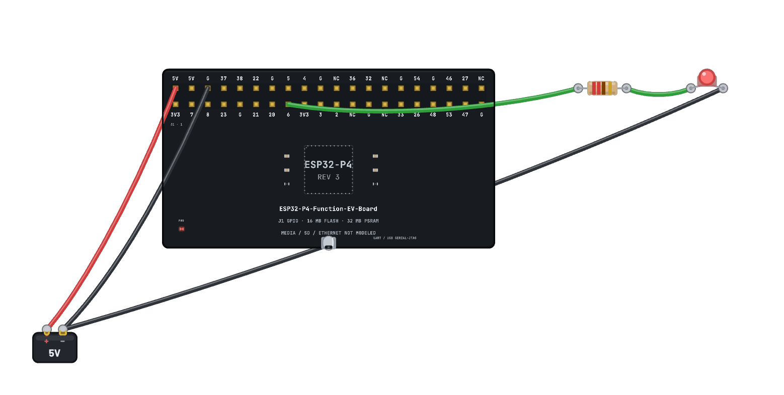 ESP32-P4 Arduino blinkTwo real RISC-V cores run a compiled Arduino sketch and blink an external LED on J1 GPIO6. The P4 has no emulated radio. Its 40-position J1 header follows the physical Function EV Board v1.5.2, including the NC contacts.
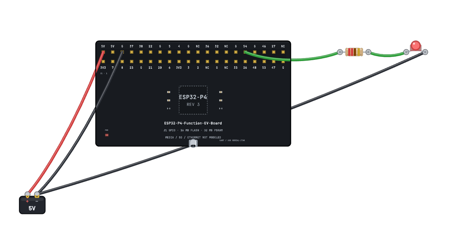 ESP32-P4 MicroPython GPIO54The pinned v1.29.0 rev3 UART/USB Serial-JTAG build runs Python on the P4 and blinks GPIO54, above the first 32 GPIOs. Edit the program in Code or type into its live REPL. Random and SSL material repeat across identical runs; they are not cryptographic entropy.
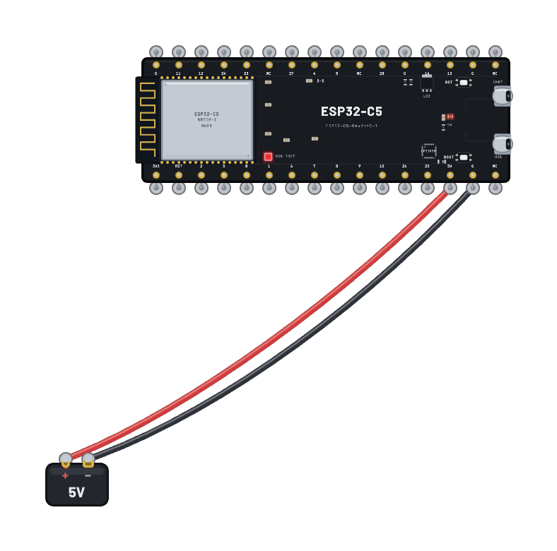 ESP32-C5 blinkA real emulated ESP32-C5 (single RISC-V RV32IMAC at 240 MHz) runs the bundled chip-specific firmware and blinks its onboard G27 RGB pixel. The C5 is the bench’s only dual-band board: its Wi-Fi 6 station sees 5 GHz networks that no other board here can hear, and it also carries an 802.15.4 radio for Thread and Zigbee.
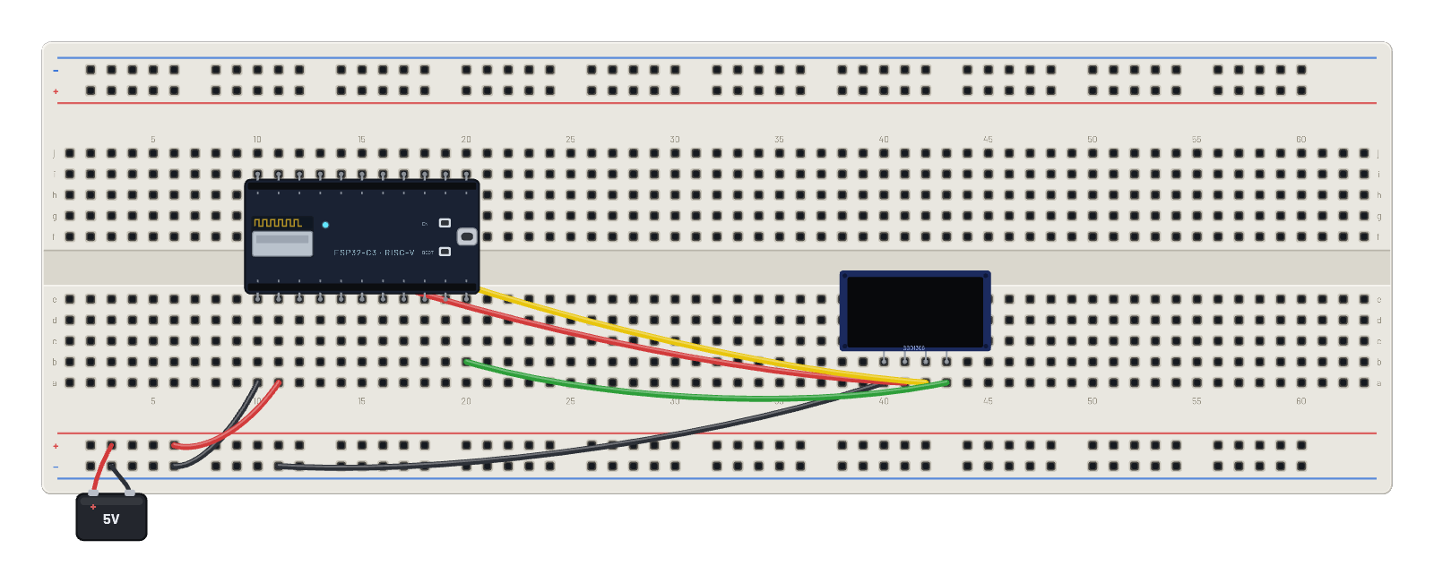 Wi-Fi: scan & join a network (OLED)Boot the actual Espressif Wi-Fi stack, scan the virtual ether, associate with BreadboardNet and get a DHCP lease, then render the live link (SSID, IP, channel, RSSI) to an OLED. Open the 📡 Sniffer to watch every frame, and click the board for its radio state.
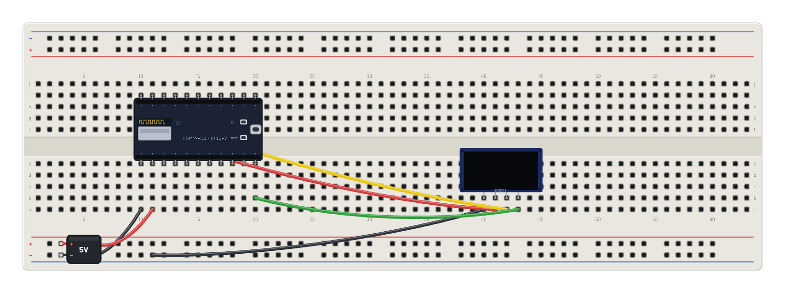 Weather over the sandbox internet (OLED)The board is really online, inside the sandbox internet. The ESP32 joins Wi-Fi, resolves api.weather.test with a real DNS lookup, and GETs a weather JSON over a genuine TCP socket — then fills a 128×128 OLED like a proper station: location, sky, temperature, humidity, wind, a live temperature-trend sparkline, and a UTC clock from a second REST call. Everything is deterministic and offline (the sandbox mocks the services), so this bench needs no account and stays on the sandbox internet — its api.weather.test host exists only in the emulator. For the same demo against a live API, open “Weather over the real internet (Pro)”. Follow every lookup and HTTP exchange in the 📡 Sniffer.
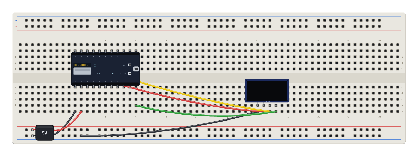 Weather over the real internet (Pro)The same socket code as the sandbox examples, pointed at the REAL internet: the ESP32 GETs live weather from api.open-meteo.com (a curated, allowlisted host, no API key). NOTE: real access needs a signed-in Pro account: click the ESP32 and flip its Wi-Fi inspector from 🧪 Sandbox to 🌐 Real internet; requests then travel through the secure egress gateway (TLS added at the edge, deny-by-default allowlist, daily quota). Until then the bench stays in the sandbox and the screen shows exactly how to go live. Change the city in the Code tab.
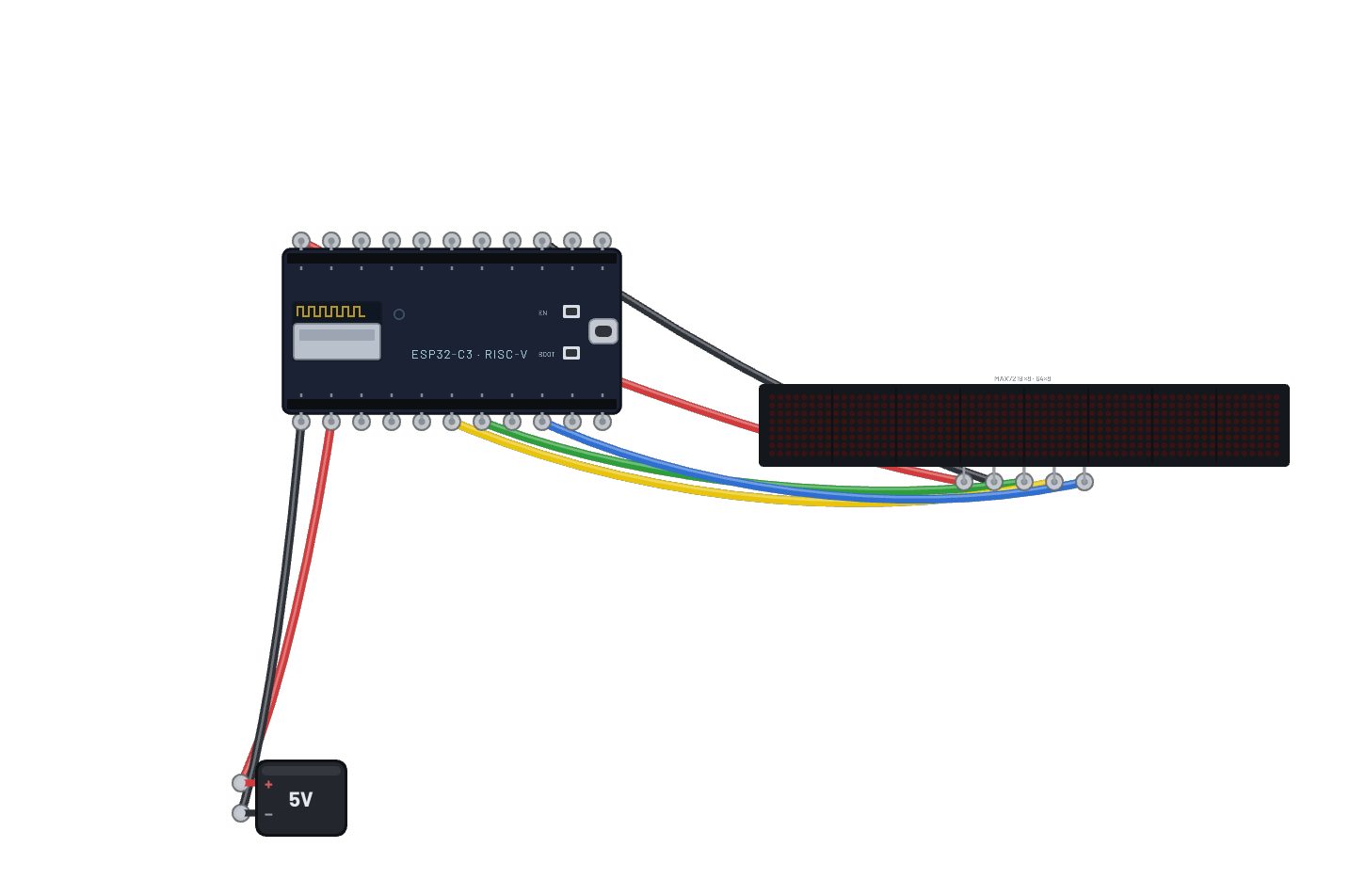 Stocks over the sandbox internet (LED matrix)A finance ticker on the big 8-in-1 MAX7219 bar: the ESP32-C6 fetches quotes from the sandbox internet’s mock exchange (prices tick on a deterministic walk every 5 seconds) and scrolls symbol, price, and change across 64×8 LEDs over hardware SPI. The scroll re-fetches at every wrap, so watch the numbers move; the serial monitor prints each refresh.
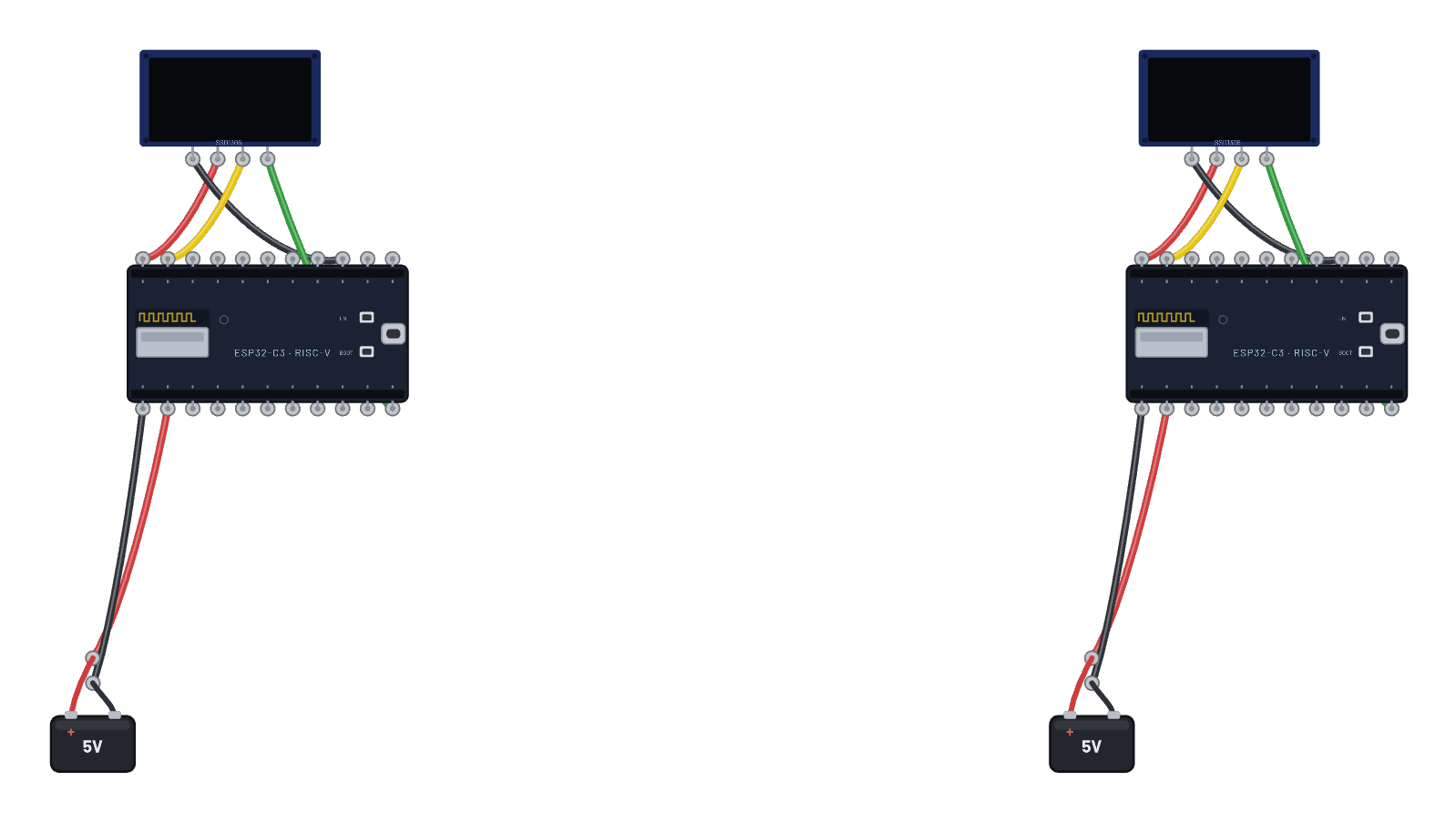 ESP-NOW pair: two boards talkingTwo ESP32-C3 boards share the virtual air and ping-pong ESP-NOW messages, each showing its own TX/RX tally and the last message received on its OLED. Watch the glowing packets fly between the chips, follow every frame in the 📡 Sniffer, and click either board for its radio state. One script runs on both; each derives its peer from its own MAC.
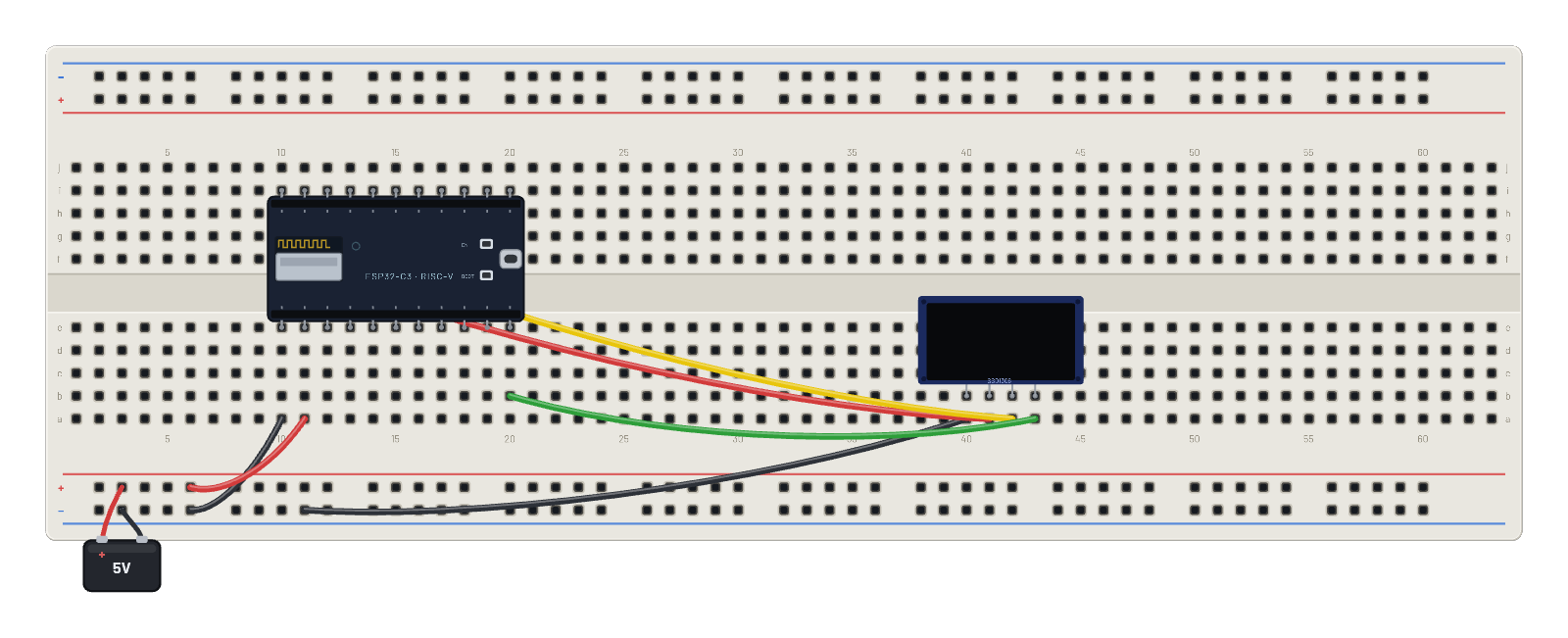 WPA2 secure join (OLED)Join a password-protected network and watch the real WPA2 4-way handshake happen: the unmodified supplicant runs genuine PBKDF2/AES against the virtual AP. The OLED shows a padlock, the SSID and the leased IP over the encrypted link; the 📡 Sniffer shows EAPOL messages 1–4 then DHCP over CCMP.
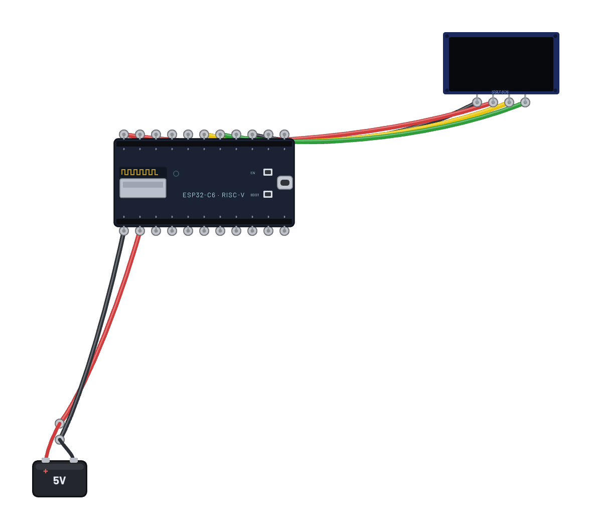 Wi-Fi 6 on the ESP32-C6 (OLED)The RISC-V ESP32-C6 boots its real 802.11ax station stack, scans the virtual ether, joins BreadboardNet and leases an address over DHCP, then renders the live link (SSID, IP, channel, RSSI) to an OLED on the C6 pins (SDA G23, SCL G22). Open the 📡 Sniffer to watch every frame, and click the board to inspect all three of its radios: Wi-Fi, Bluetooth LE and the 802.15.4 MAC that Thread and Zigbee share.
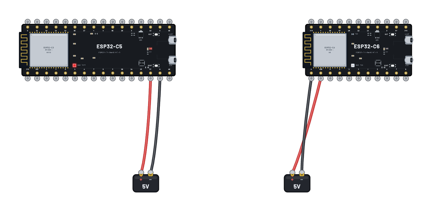 Dual-band Wi-Fi: 5 GHz on the ESP32-C5Two boards, one radio environment, one script — and two different answers. The ESP32-C5 and the ESP32-C6 are each given the same two networks (Breadboard-2G on channel 6 and Breadboard-5G on channel 36), boot their own MicroPython image, and scan. The C5 is the bench’s only dual-band station, so it reports both; the C6’s 2.4 GHz-only radio genuinely never hears the 5 GHz beacons, and its scan comes back one network short. Read the two RESULT lines in the serial monitor against each other. Both boards carry the identical network list in their Wi-Fi inspector — the channel-36 row is right there on the C6 as well, labelled 5 GHz, and its radio still cannot hear it.
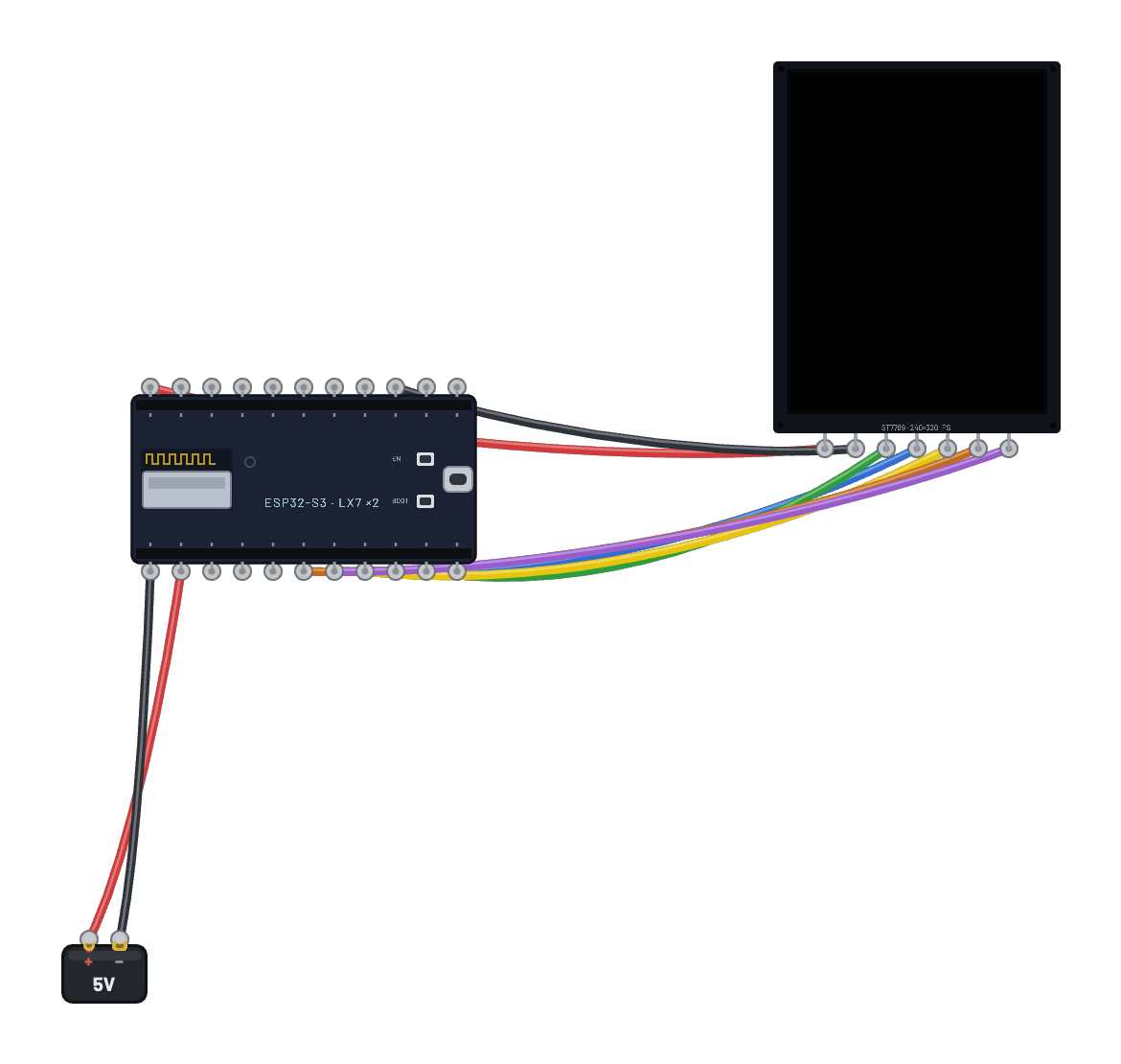 A tiny AI storyteller (ESP32-S3)A real 28.9-million-parameter TinyStories language model (slvDev/esp32-ai, MIT) running entirely on the emulated ESP32-S3: the 15.5 MB app image with the embedded model fills a 16 MB flash chip, the int8-staged weights and KV cache live in the 8 MB octal PSRAM, and both LX7 cores split every matrix row. The story streams to the big 2.8″ color TFT — your prompt in yellow, the tale in white, and a live tokens-per-second footer fed over real hardware SPI (every pixel costs honest bus time). Type a few words into the serial monitor and press Enter: the model tokenizes your prompt on-device and writes you a new story at its true hardware-class rate, ~8 tokens/second with the panel attached, courtesy of the JIT that compiles the hot int8 dot-product loop to WebAssembly on the fly.
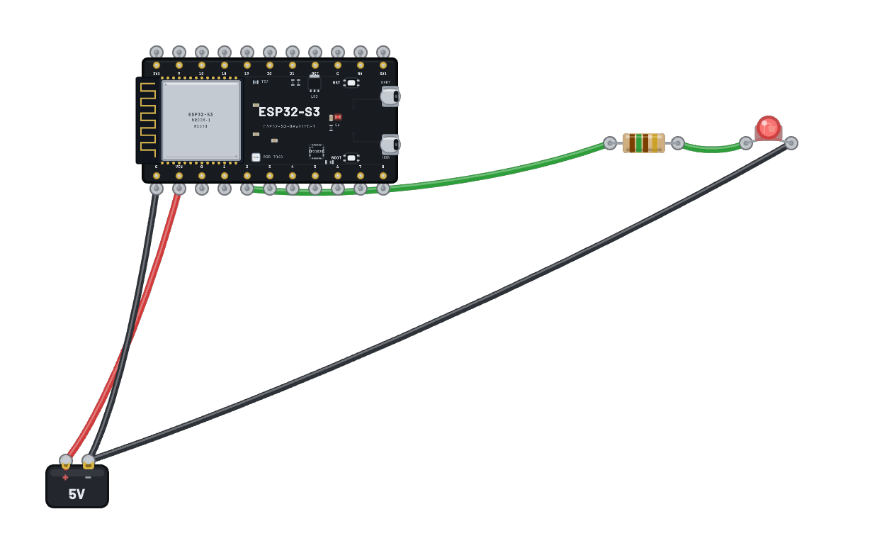 ESP-IDF project · ESP32-S3Your own ESP-IDF v5.3.5 project on a real emulated ESP32-S3 N16R8: the Code tab holds the C sources under main/ (add, rename and delete files), and Compile & run rebuilds them on a fixed, pre-built project in the cloud in about half a minute. The bundled firmware is the unedited starter: it prints a greeting and blinks the LED on G2 every half second. Components you may include are listed in main/CMakeLists.txt; CMake and sdkconfig stay fixed.
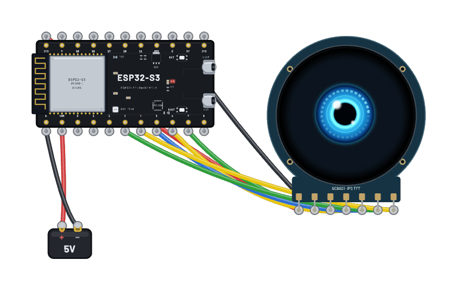 Round eye (ESP32-S3 + round TFT)A glowing robot eye roams a 1.28″ round IPS TFT LCD at 60 frames per second: quick darts and slow glides, a scanning lens ring, blinks and changing moods. Original C firmware on the emulated ESP32-S3 redraws only what changed and streams it through SPI DMA to a GC9A01A. A fixed random seed makes every run identical; there is no network connection or external asset. Open Code to read the complete project, including the Apache-2.0 Espressif display driver.
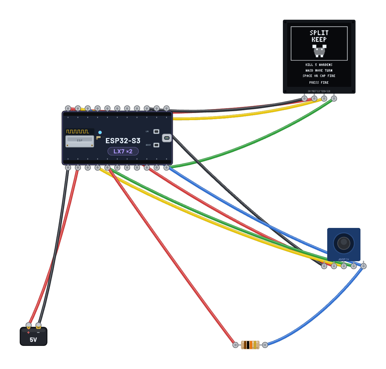 OLED dungeon (ESP32-S3 + joystick)An original first-party monochrome raycasting game running as real ESP-IDF firmware on the emulated ESP32-S3. Choose Select, focus the canvas, and use WASD to move/turn plus Space to fire; or drag the physical joystick cap and click it without moving to fire. The fixed 20 Hz game loop samples real ADC1/GPIO input on G1, G2, and G10, renders a complete 128×128 page-major frame, and sends it over hardware I²C on G8/G9 to the real 1.5″ SH1107 model. Split Keep opens with a visible horned warden, then branches through auto-opening doors and north/south routes; clear five wardens to unlock the exit while hunting health and ammunition. Muzzle flash, hit and damage feedback, an objective HUD, win/death screens, and deterministic restart all run on-device. It needs no account, backend, internet, colour display, or PSRAM; the Code tab shows the complete MIT source and portable host harness read-only.
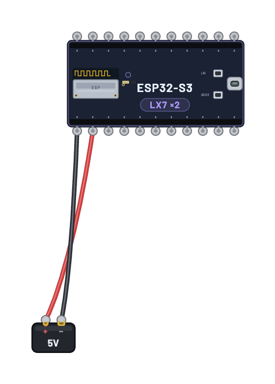 Storyteller from source (ESP-IDF)A real multi-file ESP-IDF C project you can read, edit and rebuild: a line-faithful port of Andrej Karpathy’s llama2.c running the 260K-parameter TinyStories model on the emulated ESP32-S3. The board boots and writes a deterministic story to the serial monitor, then takes your typed prompt and writes another. The Code tab holds the exact C source, CMake files, sdkconfig and partition table the firmware was built from — change the boot banner or the sampling loop, press Compile & run, and the cloud sandbox rebuilds the firmware with ESP-IDF v5.3.5 and boots your build on the bench.
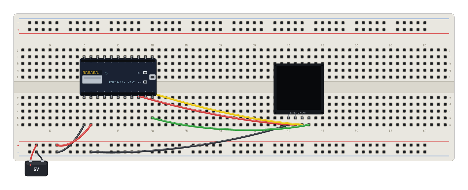 HTTP fetch on the ESP32-S3 (OLED)The dual-core ESP32-S3 boots the real Wi-Fi stack on both LX7 cores, joins BreadboardNet, and fetches a page from the in-core virtual server over a genuine TCP socket, rendering the status, response body, and a live request counter to a big 1.5″ 128×128 OLED, re-fetching every couple of seconds. Open the 📡 Sniffer to follow the whole conversation: SYN/ACK, the GET, the streamed response, and the FIN teardown.
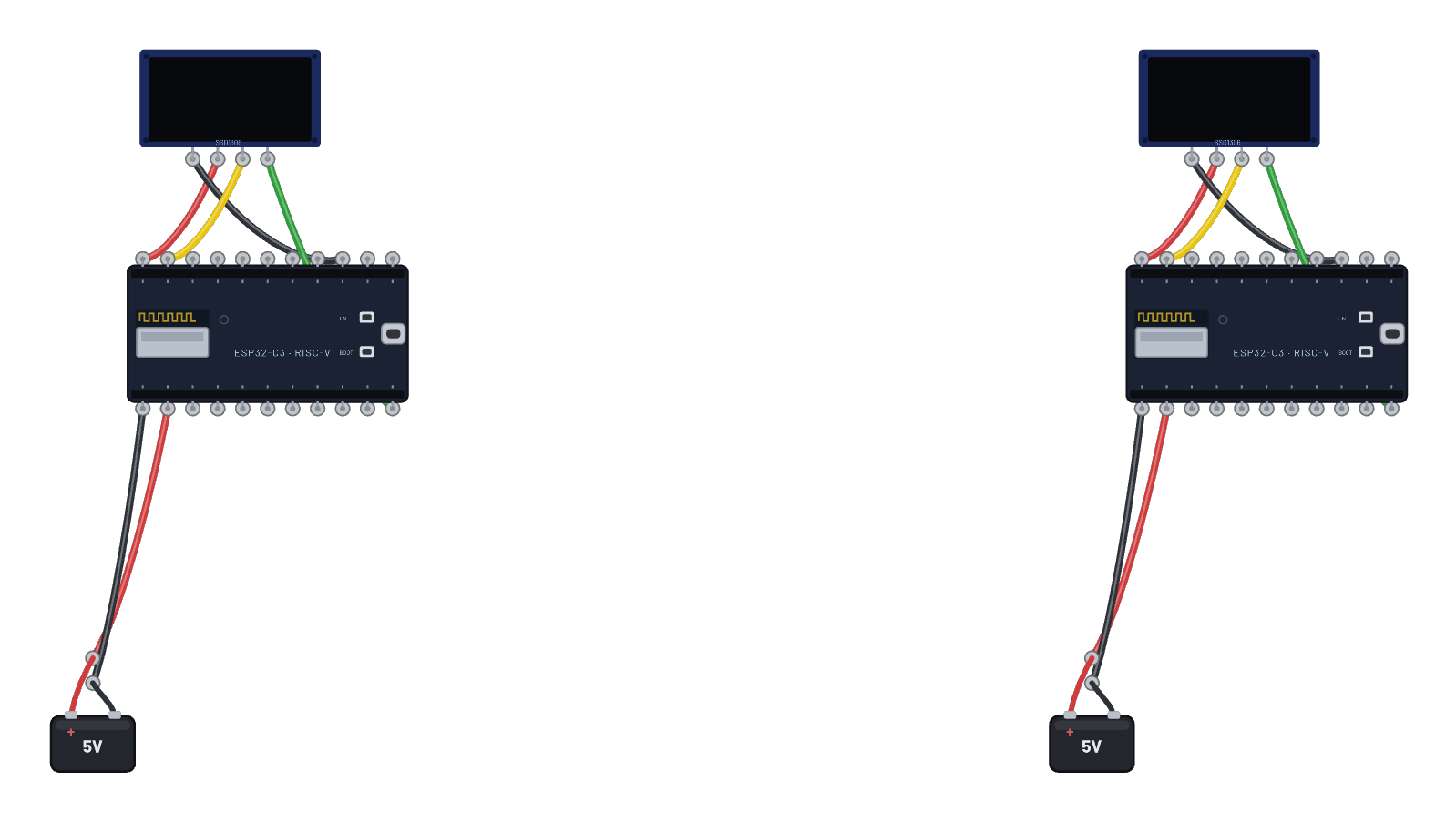 Two boards: HTTP server + clientBoard B runs a real MicroPython socket server; board A fetches from it every 1.5 s. The boards lease unique addresses (192.168.4.2 and .3) and every hop (ARP, SYN, the request, the reply) is a genuine 802.11 frame relayed across the virtual air, two real lwIP stacks end to end. Open the 📡 Sniffer and the per-board serial tabs to watch both sides.
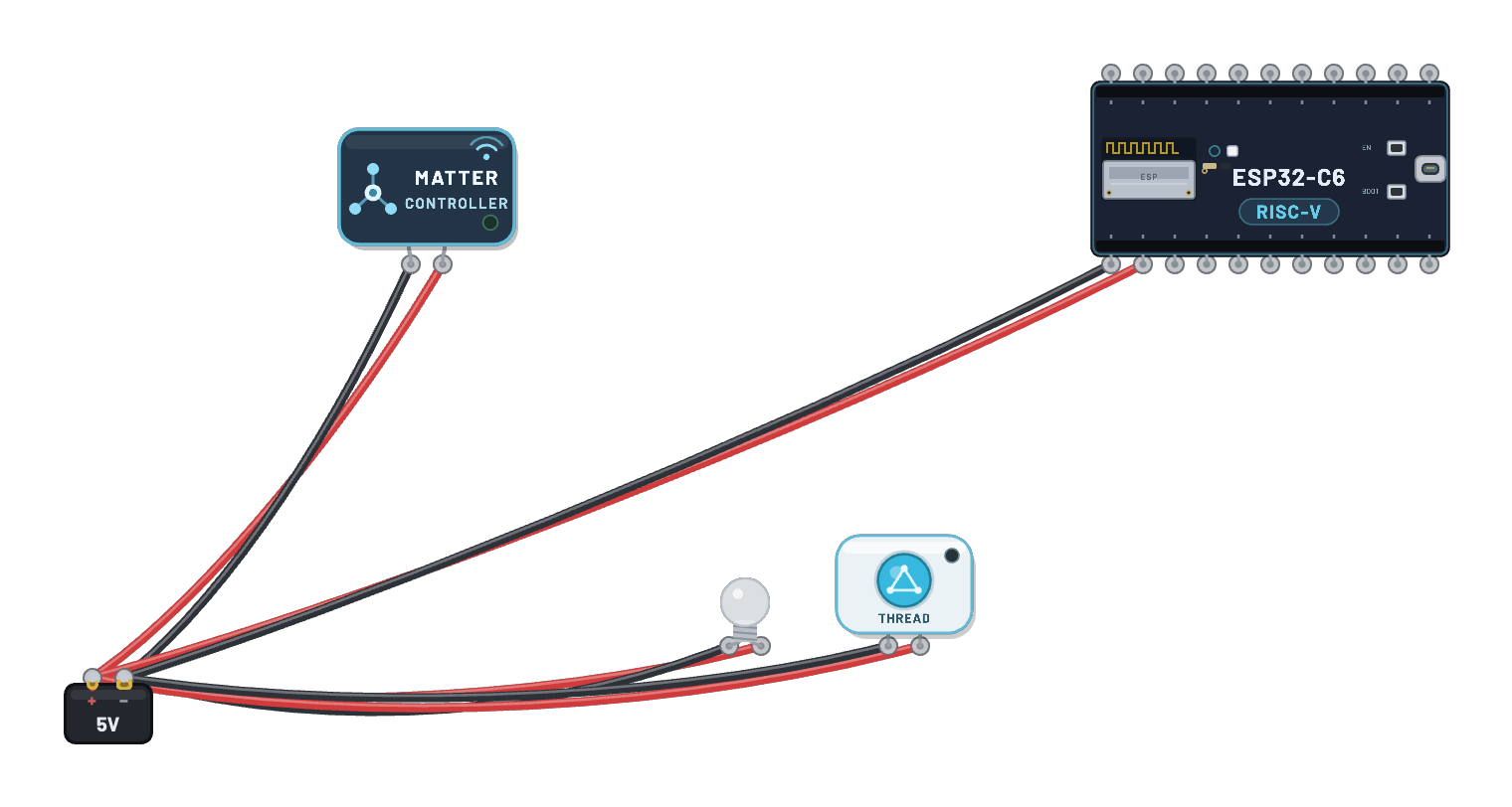 Matter-over-Thread: commission a bulbA real smart-home stack, end to end: an ESP32-S3 Matter controller, a C6 Thread Border Router, and a sealed Matter bulb — three unmodified vendor firmware images, plus a powered Thread control button for the controller. The example sets itself up: guided steps connect Wi-Fi, forms the Thread network, and commissions the bulb over Bluetooth LE with a real PASE handshake. Then press the wired-and-powered control button (or click the bulb) — every press enters the real controller firmware and sends a Matter command over Thread; the glass lights only when it reaches the bulb firmware’s GPIO8 output. The 📡 Sniffer separates BLE commissioning from Thread traffic; test credentials only, with no certification or physical-ecosystem claim.
 OpenThread: a real Thread nodeA real emulated ESP32-C6 running the unmodified OpenThread stack. No typing needed: the sketch commits a complete operational dataset in setup() and starts Thread, so the node comes up as leader on its own; the radio encrypts its MLE traffic with the real hardware AES-CCM* path. The full OpenThread CLI stays on the serial monitor (`state`, `dataset active`, `ipaddr`), the Code tab holds the exact sketch the firmware was built from, and the 📡 Sniffer shows the 802.15.4 frames. Open the Thread mesh example to see a second board join it.
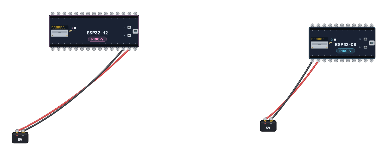 OpenThread: H2 node + C6 leaderThe Wi-Fi-free ESP32-H2 joins a real Thread mesh with an ESP32-C6. The C6 auto-forms the fixed Breadboard network as leader; after eight seconds the H2 commits the matching dataset and attaches as a child over MAC-secured MLE. No typing needed. Both serial tabs narrate their roles and keep a full OpenThread CLI, the Code tab shows both exact Arduino sketches, and the 📡 Sniffer shows their bidirectional 802.15.4 traffic.
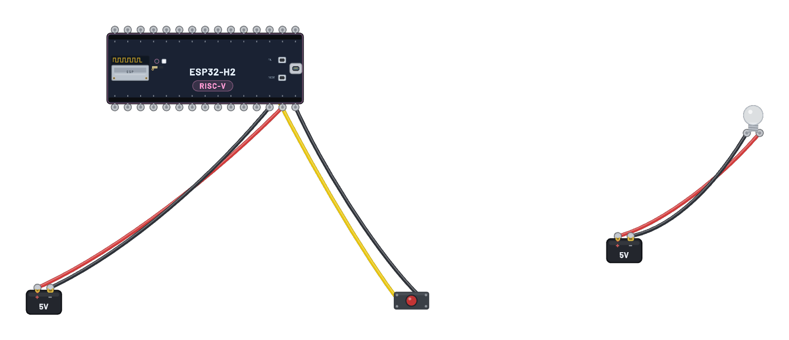 Zigbee: H2 switch + C6 smart bulbAn ESP32-H2 runs the real esp-zigbee coordinator/router firmware and the existing sealed smart bulb keeps its genuine C6 appliance core. The H2 forms the network and binds the joining light; then CLICK AND HOLD THE BUTTON briefly and a real ZCL Toggle crosses the shared 802.15.4 air to light the glass. The Code tab shows the coordinator sketch and the 📡 Sniffer exposes the join, binding, and on/off frames. (The join takes a moment.)
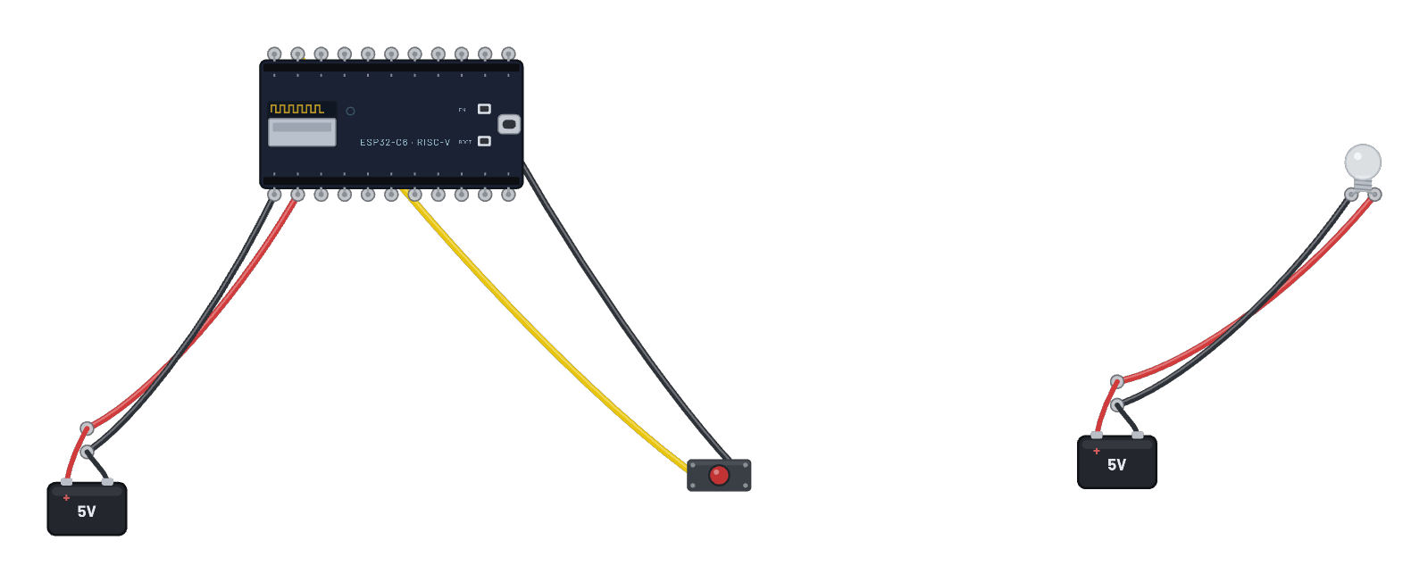 Zigbee network: smart bulb + switchA real smart bulb on the bench: the sealed lamp hides a genuine emulated ESP32-C6 running esp-zigbee light firmware, exactly like the SoC inside a Hue or IKEA bulb. The C6 board is the coordinator (switch); the bulb joins its network over the shared 802.15.4 air, gets bound, and then CLICK AND HOLD THE BUTTON briefly: a real ZCL Toggle crosses the air and the glass lights up. Click the bulb to see its join state and light level, and follow the join in the 📡 Sniffer. (The join takes a moment.)
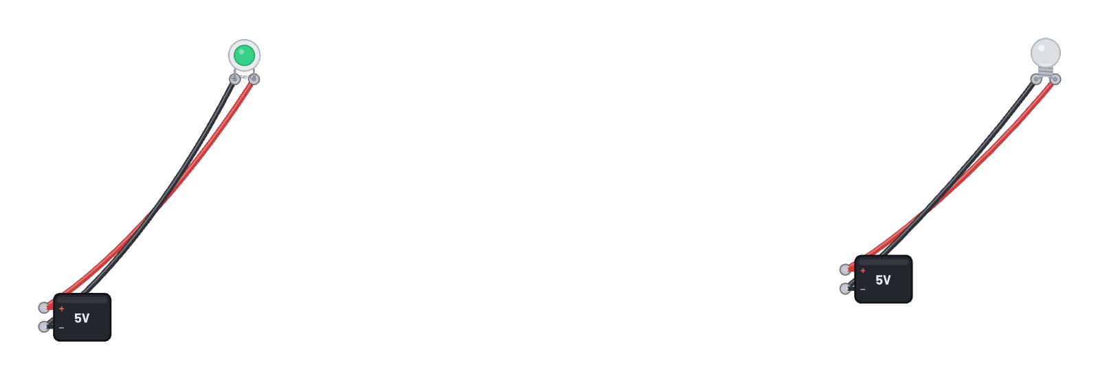 Zigbee smart button + bulbTwo sealed products, no DevKit: a wireless smart button and the bulb it controls, each a real emulated ESP32-C6. The button puck is the coordinator: it forms the network, the bulb joins and binds, and then CLICK AND HOLD THE PUCK briefly: a real ZCL Toggle crosses the 802.15.4 air and the glass lights. Click the bulb for its live join state, and follow the join and toggle in the 📡 Sniffer. (The join takes a moment.)
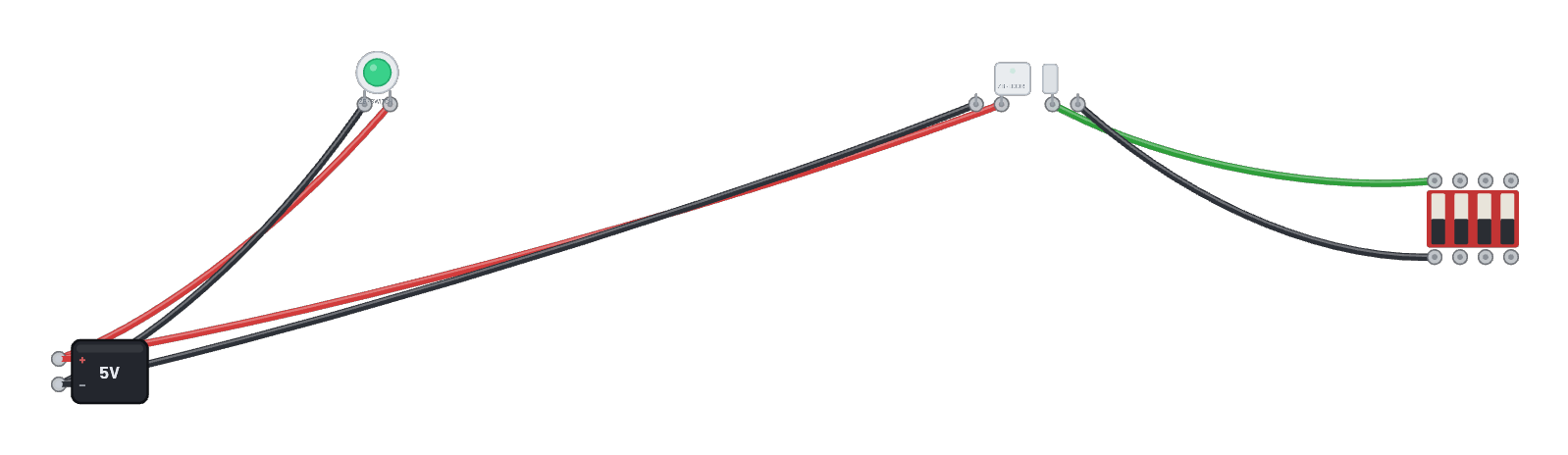 Zigbee door sensor + smart buttonA door/window sensor as a sealed product: the C6 inside runs esp-zigbee IAS-zone firmware, and the smart-button puck (the coordinator) forms the network it joins. The DIP switch across the contact terminals plays the door: flip it and the sensor reports a genuine zone-status change over the air (watch its serial tab and the 📡 Sniffer). Click the sensor for its live join + contact state.
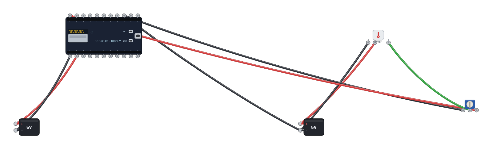 Zigbee temperature sensor + hubThe reporting direction of Zigbee: a sealed battery-style temperature sensor joins the thermostat hub and reports over the standard temperature-measurement cluster. The trim pot on its probe (0–3.3 V = −10…+50 °C) is the temperature dial: drag it and watch the hub’s serial tab print each received report. Both firmware sketches are in the Code tab.
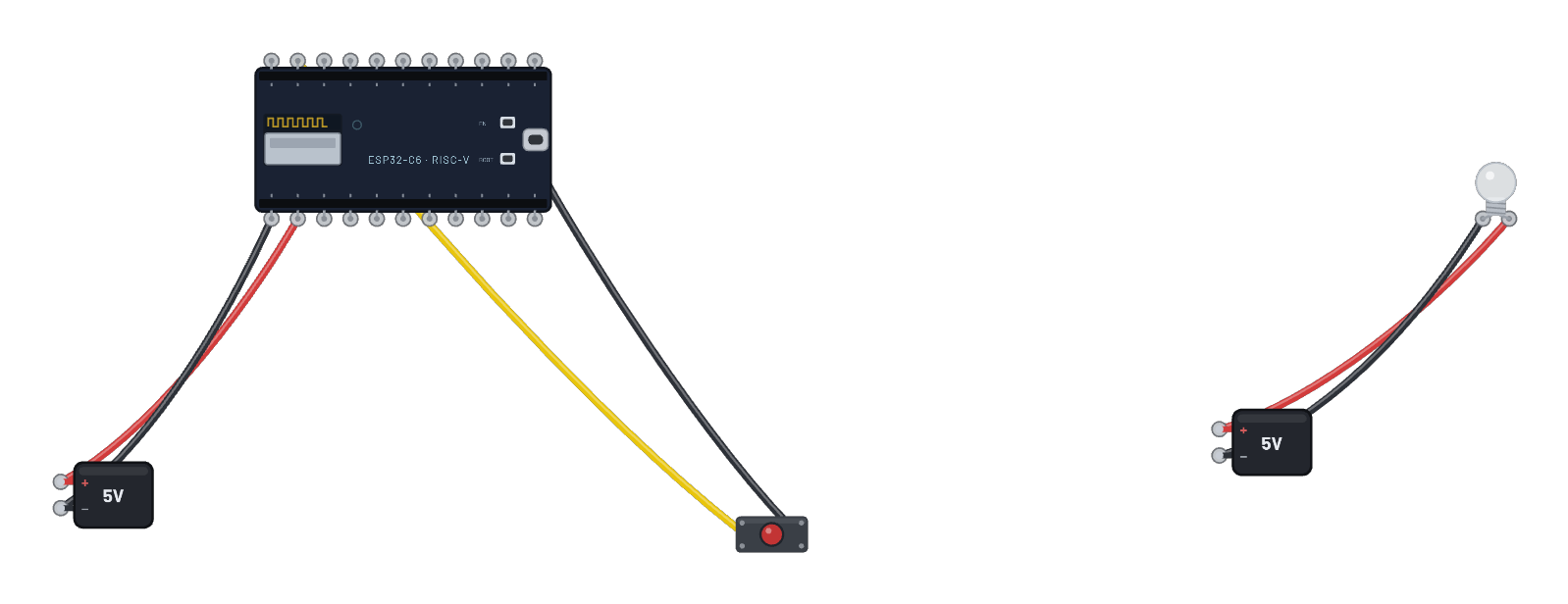 Zigbee color bulb light showThe bulb goes full color: a color-dimmable light (real ZCL Color + Level clusters) joins the color-remote coordinator, which then walks it through a color wheel, a new hue every few seconds, no typing. Press the remote’s button to toggle the bulb; click the bulb for its live color. Both sketches are in the Code tab; every color command is a real 802.15.4 frame in the 📡 Sniffer.
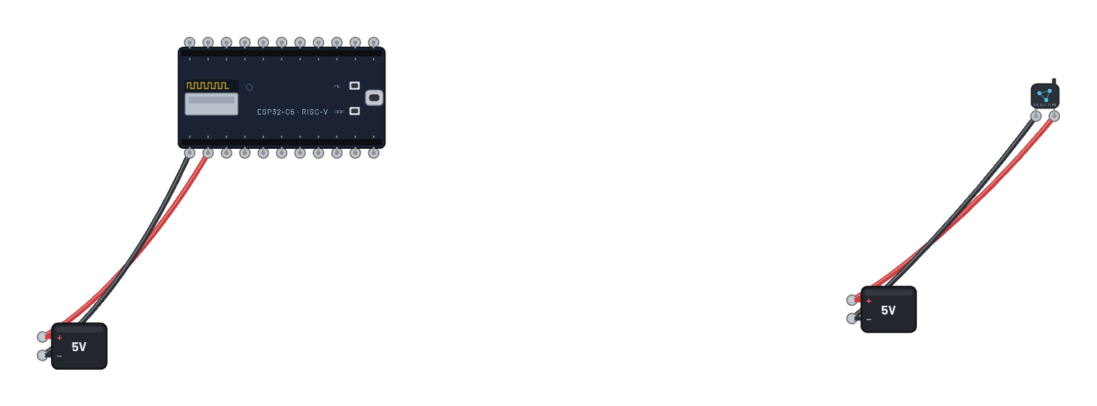 Thread sensor network (hub + node)Thread made visible: the hub DevKit forms the network as leader and listens on UDP, and the sealed sensor node attaches as its child and reports its temperature every 5 seconds, each report a MAC-secured 802.15.4 frame you can follow in the 📡 Sniffer. Watch the hub’s serial tab print every datagram; the full OpenThread CLI stays available there (`child table`, `ipaddr`). Both sketches are in the Code tab.
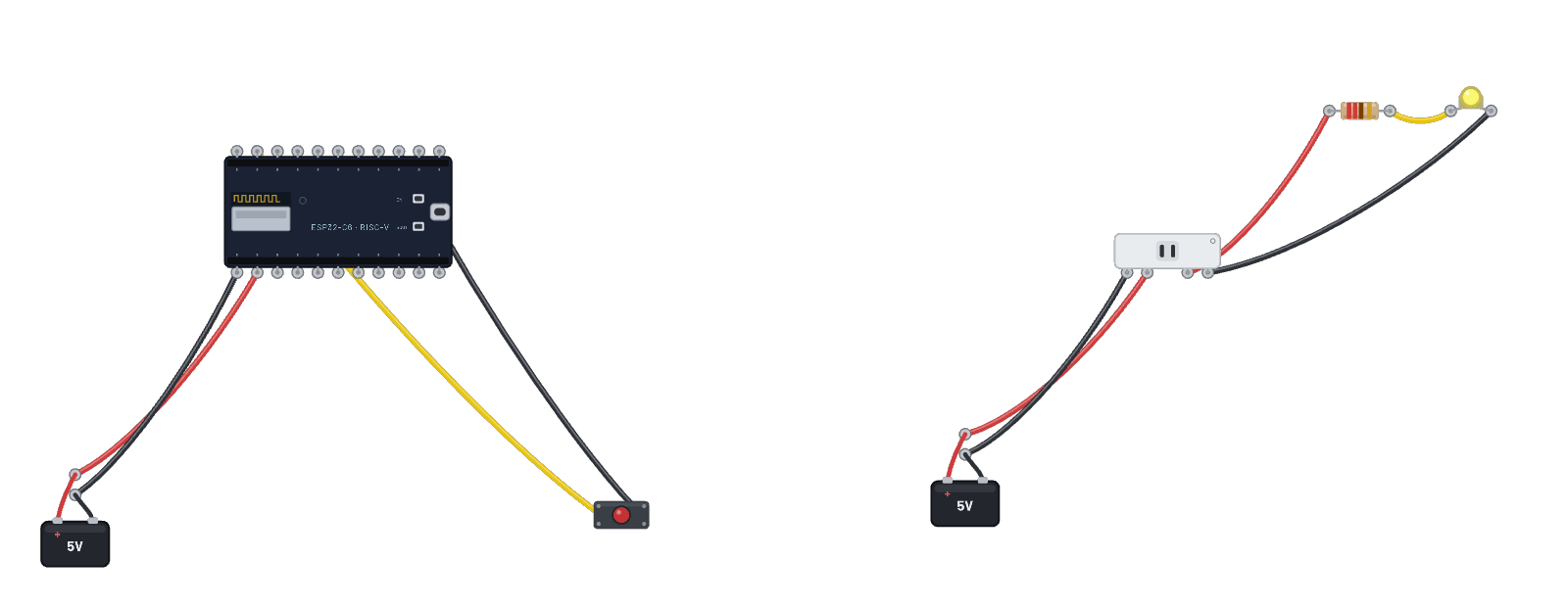 Zigbee smart plug + lampThe smart bulb's sibling: a Zigbee plug whose sealed shell hides a genuine emulated ESP32-C6. The plug's outlet REALLY switches — its live pin carries nothing until the coordinator toggles it. A dumb lamp (LED + resistor) hangs off the outlet; CLICK AND HOLD THE BUTTON briefly and a real ZCL Toggle crosses the air, the contact closes, and the lamp lights because current actually flows. Click the plug for its join and outlet state. (The join takes a moment.)
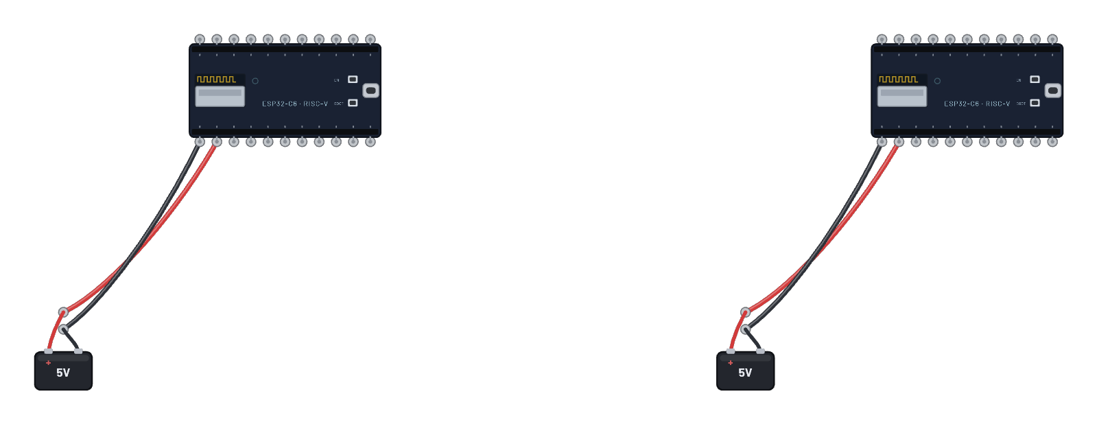 Thread mesh: two nodesTwo ESP32-C6 boards running OpenThread on the shared air, and they mesh by themselves. Board 1 commits a complete dataset and forms the network as leader; board 2 carries only the network key, hears the leader and attaches as its child, exchanging MAC-secured MLE frames the whole way. Each serial tab narrates its board’s role changes and keeps the full OpenThread CLI (`state`, `parent`, `child table`); the Code tab holds both real sketches, and the 📡 Sniffer shows every frame.
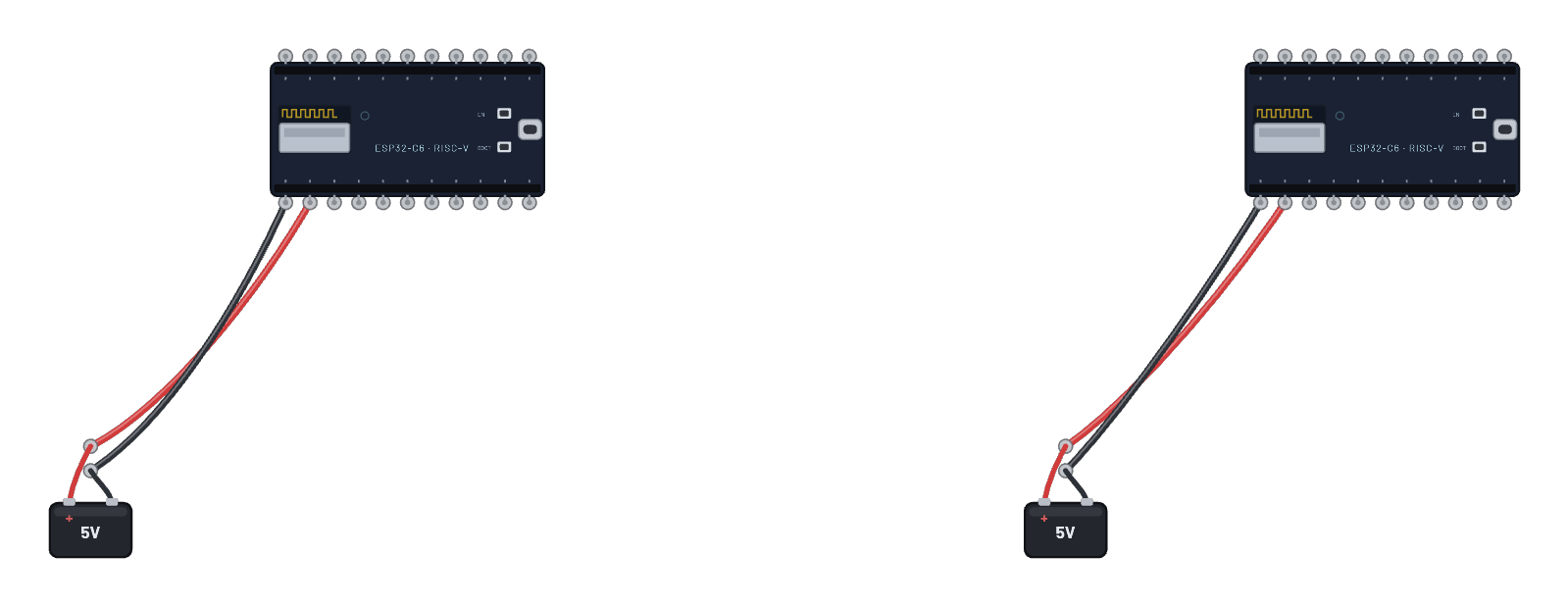 Bluetooth LE: scan, connect, discoverTwo ESP32-C6 boards run the full BLE story through the real vendor controller: one registers a Battery Service and advertises connectably, the other scans, hears the advertisement, connects as central over a genuine LE link, and discovers the server's GATT services. One script runs on both boards; each derives its role from its own MAC. Watch the serial tabs narrate both sides, follow ADV_IND / CONNECT_IND / ATT frames in the 📡 Sniffer, and click either board's Bluetooth tab for its live link state.
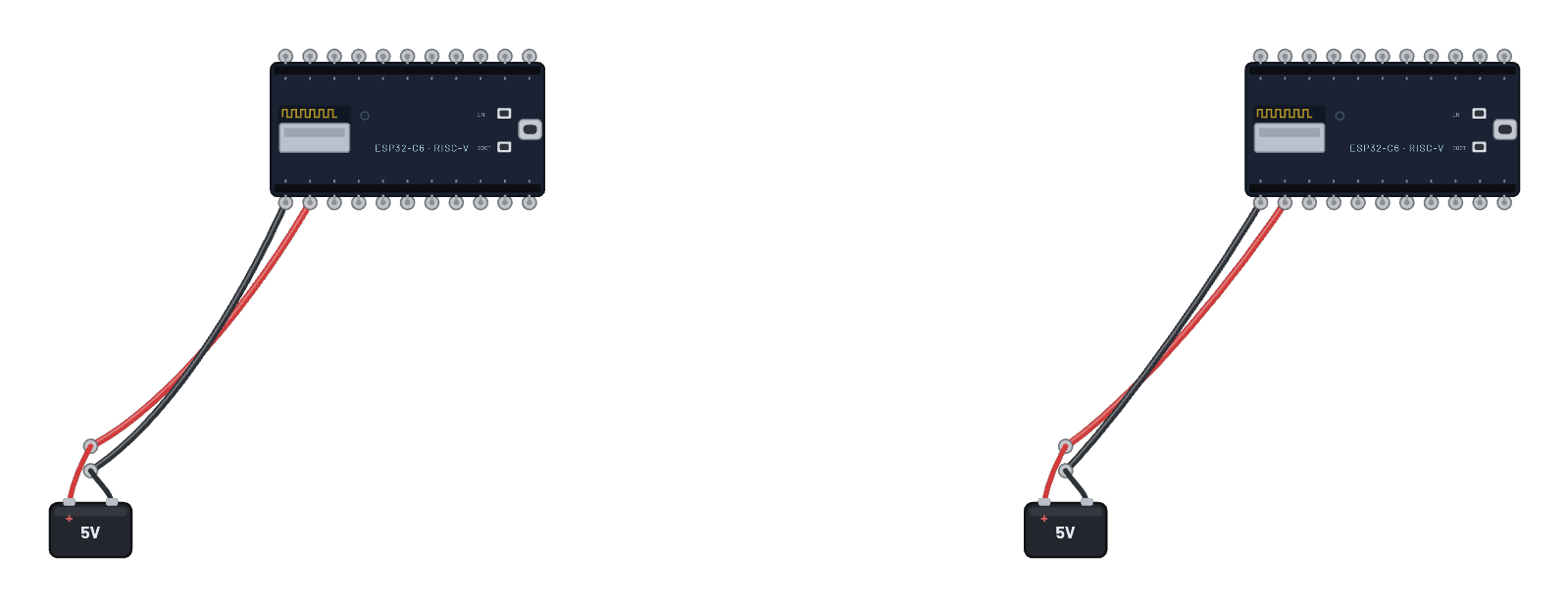 Bluetooth LE: pair & encryptTwo ESP32-C6 boards secure a real LE link end-to-end: one advertises connectably, the other connects as central and calls gap_pair. The SMP Just-Works handshake runs over the link (watch the SMP frames in the Sniffer), the controllers derive the key and run the LL encryption-start procedure, and BOTH boards report _IRQ_ENCRYPTION_UPDATE with a 16-byte key; the peripheral’s report rides the emulator’s post-encryption receive path through the controller’s own buffer allocator. One script on both boards; roles derive from each board’s MAC.
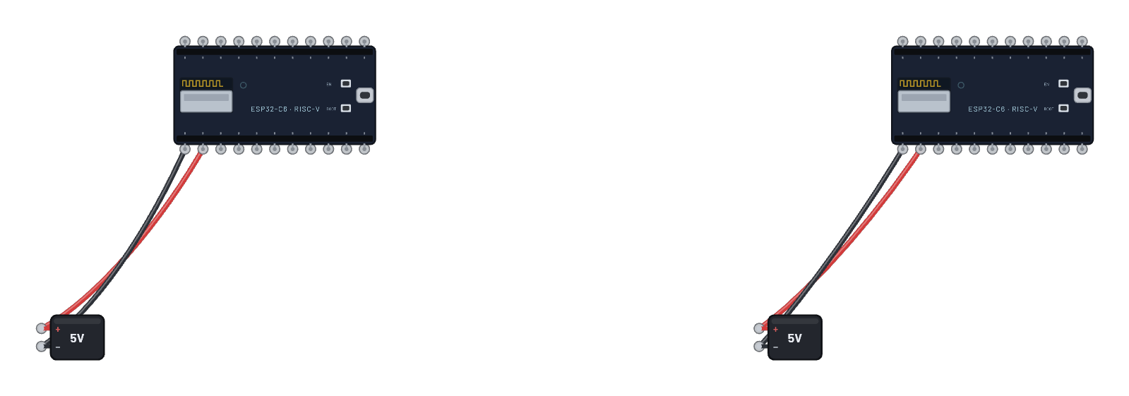 Bluetooth LE: bond & reconnectThe pairing story taken to its real-world conclusion: the boards don’t just encrypt once, they BOND. The central pairs, both hosts persist the long-term key through the secret store, then the central hangs up and comes back. On the reconnect the second gap_pair exchanges no pairing traffic at all (check the Sniffer: after the first handshake not a single SMP frame crosses); the link re-encrypts straight from the stored key, exactly how a phone greets a smartwatch it already knows. One script on both boards; roles derive from each board’s MAC.
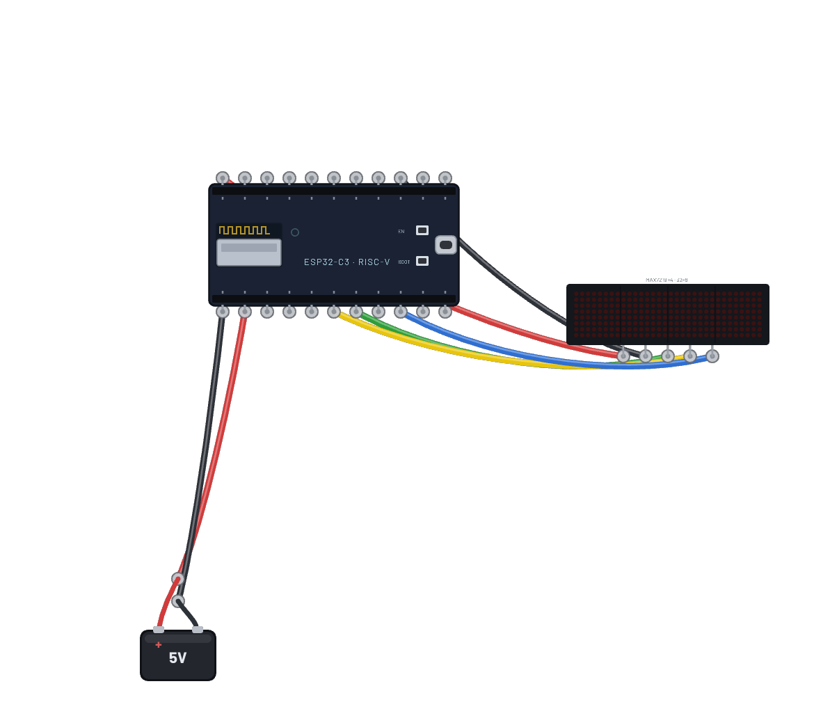 LED ticker (32×8 matrix bar)A message scrolls across the 4-in-1 cascaded MAX7219 bar, pushed over the ESP32-C6’s hardware SPI (`machine.SPI(1)` on the stock pins): a 32×8 framebuffer shifted one column per frame, exactly how the real max7219 drivers do it. Edit the message in the Code tab.
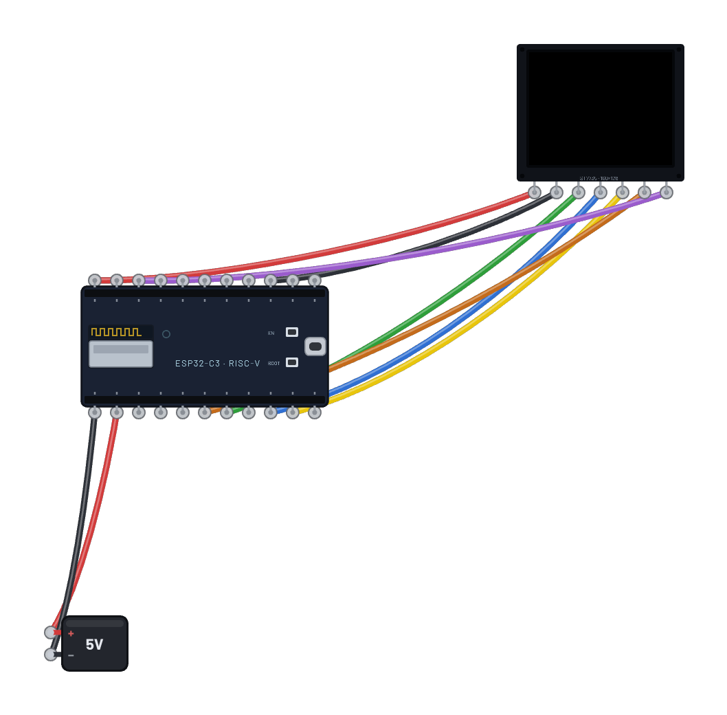 Color dashboard (ST7735 TFT)A full-color 1.8″ TFT on the bench: the ESP32-C6 drives a real ST7735 over hardware SPI (`machine.SPI(1)` on the stock pins), sets an address window (CASET/RASET) and streams a 160×128 RGB565 framebuffer per frame at bus speed, exactly like the MicroPython st7735 driver. It fetches live weather from the sandbox internet and paints a colored card: location, temperature, humidity, and conditions. Edit the colors or layout in the Code tab.
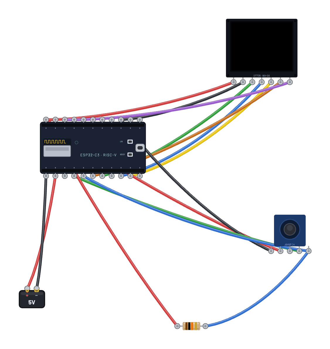 Pong (TFT + joystick)A complete, genuinely playable Pong on the 1.8″ TFT: move the joystick to steer your paddle, press its cap to serve. Real MicroPython runs the whole game — ball physics with paddle-face deflection, a beatable CPU opponent, live score, win screen and rematch — over the ESP32-C6's hardware SPI (`machine.SPI(1)` on the stock pins), streaming only dirty rects (~1 KB a frame, not the 40 KB framebuffer), the way a tight game loop treats any serial panel. First to 5. With Select active, drag the joystick cap or its surrounding dark gimbal well up or down to play; or select it, focus the canvas, and use arrows/WASD plus Space.
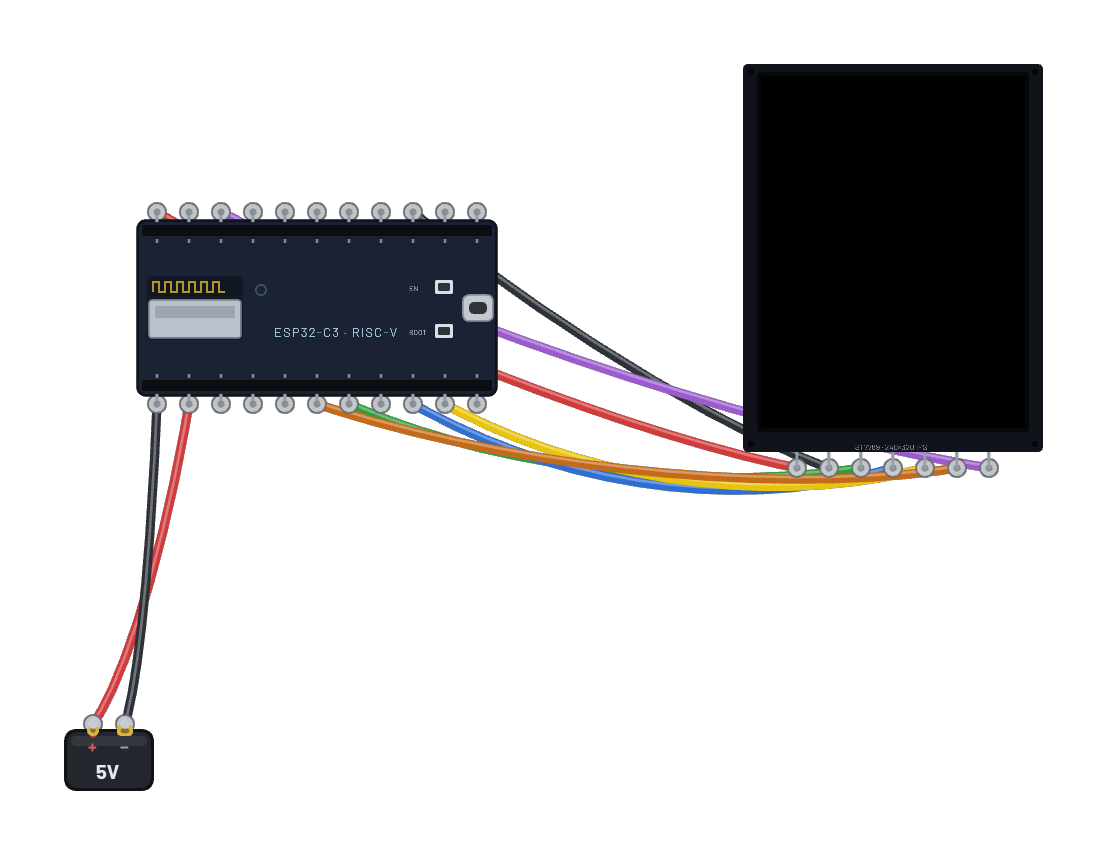 Big-screen station (ST7789 2.8″)The bench’s flagship screen: a 240×320 IPS panel showing live weather, a UTC clock, and a three-ticker market board at once, all fetched from the sandbox internet over real DNS + TCP sockets. A full frame is 150 KB — bigger than the MicroPython heap likes — so it paints in eight 240×40 strips, each blitted into its own CASET/RASET window: the exact technique real firmware uses when the panel outgrows RAM.
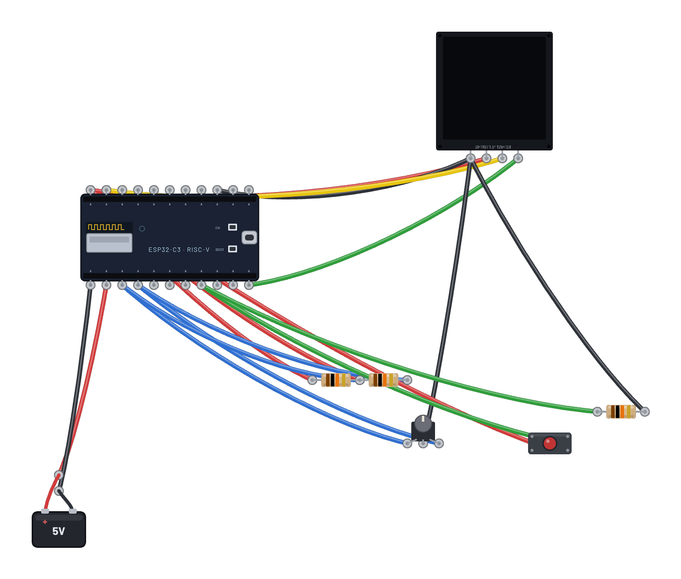 Encoder menu (big OLED)A settings page on the 1.5″ 128×128 SH1107, driven by a rotary encoder decoded in MicroPython (gray code on two GPIOs with external pull-ups). Select the encoder and use its Inspector arrows to scroll; click the button to toggle an entry.
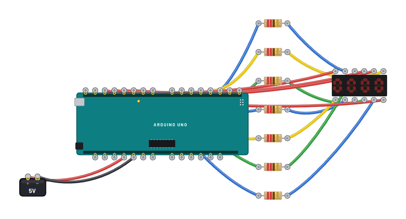 4-digit counter (7-segment)The classic 12-pin 4-digit seven-segment module, wired the honest way: eight shared segment lines through 220 Ω resistors, four digit commons straight to GPIOs. The Uno multiplexes — one digit lit at a time for 2 ms, faster than your eye — to count 0000–9999. Watch the commons on the scope to see the strobing the display hides. The Code tab holds the same logic as an editable Arduino sketch.
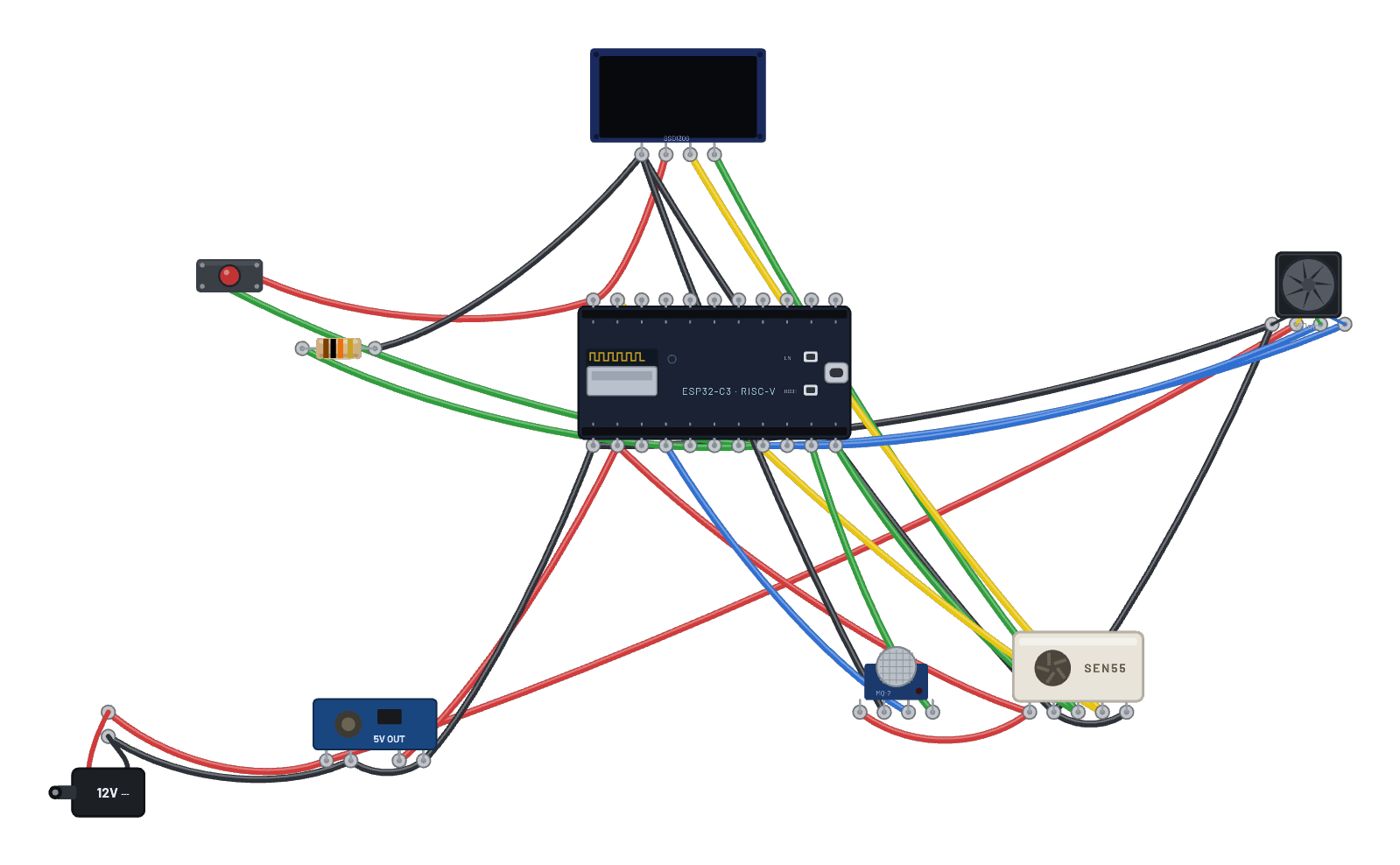 3D-printer fume extractor (ESP32, full build)The complete appliance on one bench: a 12 V barrel jack → buck converter powers an ESP32-C3 and a 120 mm PWM fan, while a Sensirion SEN55 measures the air and an MQ-2 sniffs for smoke. Real MicroPython ramps the fan from the live PM2.5, and the MQ-2 alarm (drag its Gas slider past the threshold) slams the fan to 100 % in SMOKE! mode, after the sensor’s genuine 5 s heater warm-up. Hold the boost button for manual 100 %. The code is a real multi-file project — main.py imports the display and sensor from drivers/ modules; explore the file tabs in the Code panel.
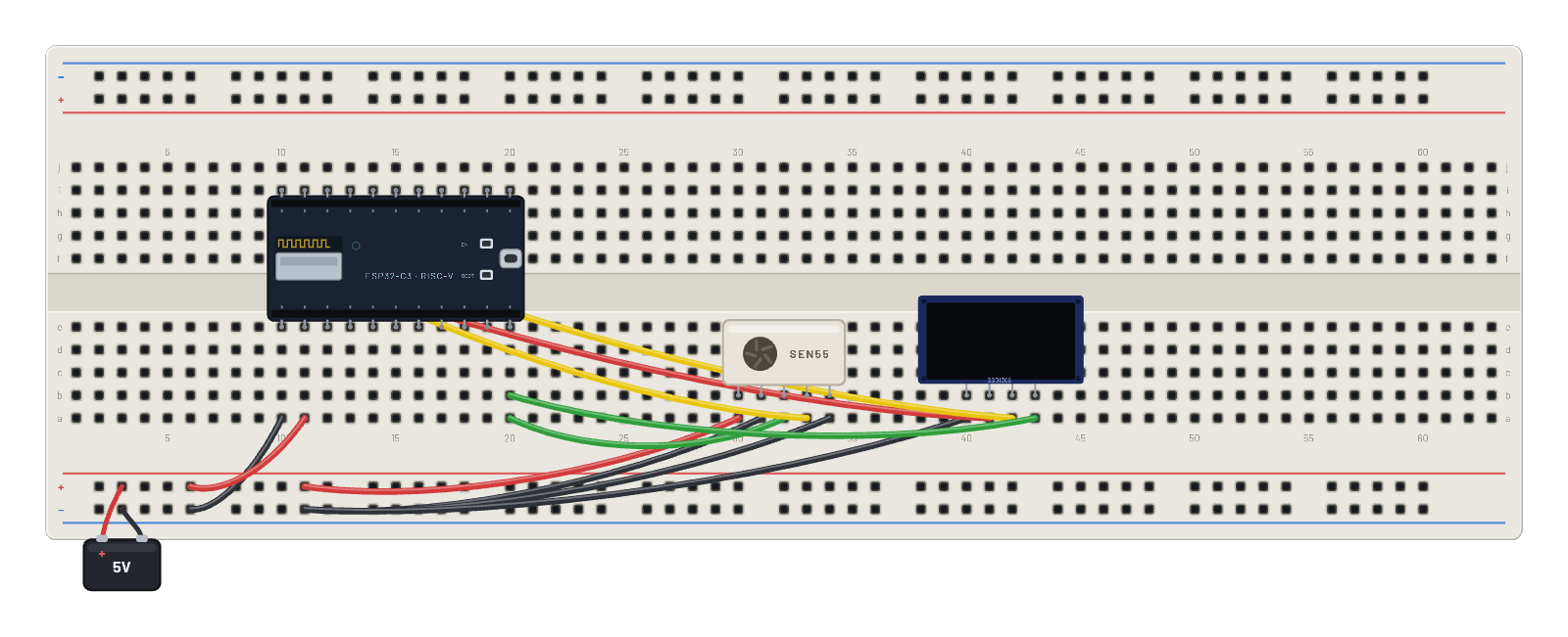 Air-quality station (SEN55 + OLED)A desk-ready monitor: the ESP32 polls a Sensirion SEN55 over I2C and renders live PM2.5, humidity, and temperature to the OLED once a second. Press Run, then ▶ Run script in the serial monitor, and the display updates like the real appliance.
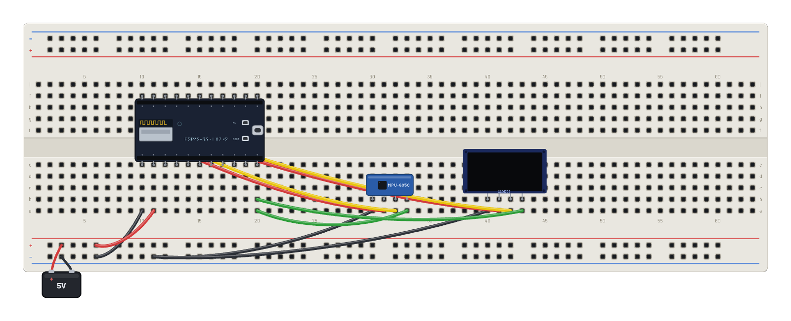 Bubble level (MPU-6050 + OLED)A spirit level built from an IMU: the S3 reads the accelerometer gravity vector and floats a bubble across the OLED. Run the prefilled script, then tilt the sensor from its Inspector (accel X/Y) and watch the bubble chase the slope.
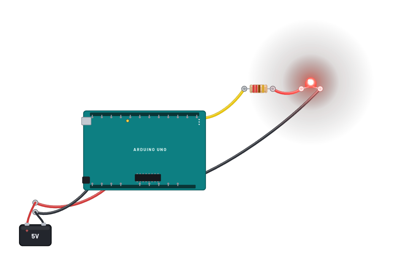 Arduino Uno R3 blink (open bench)The classic first sketch on the classic board: a real emulated ATmega328P Uno on the open bench, D13 wired to an LED pin-to-pin. The Code tab opens with the sketch; sign in and press Compile & upload to build it on the server and flash the result.
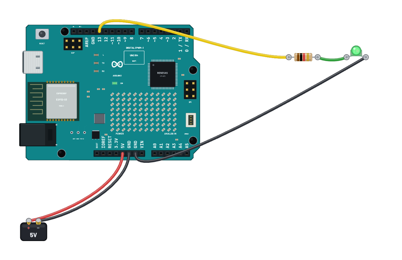 Arduino Uno R4 blinkOfficial ArduinoCore-renesas firmware runs on the real emulated RA4M1 and drives the solved 5 V D13 net. The board art includes the live cycle-observed 12×8 matrix and real D13, TX, RX and power lamps.
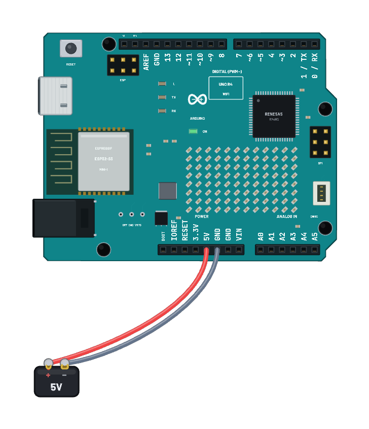 Uno R4 · USB keyboard and mouseOfficial Keyboard and Mouse libraries send Ctrl+Shift+A, uppercase B, mouse buttons and relative movement through the emulated USB controller. Select the board to see USB console and HID reports in the Inspector. Serial echoes each line you send. Reports stay inside Breadboard.
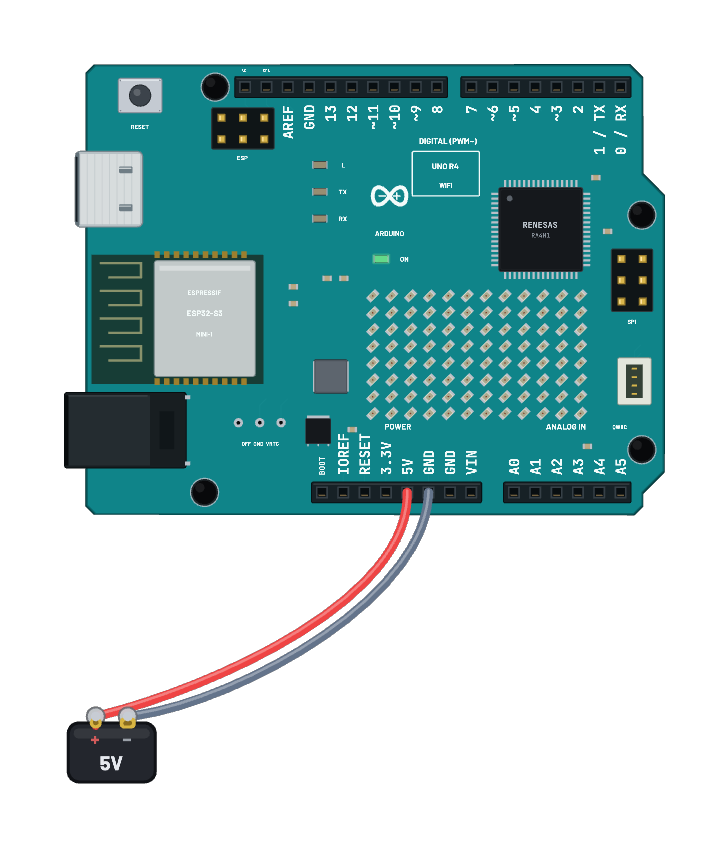 Uno R4 · HTTP and internet consentWiFiS3 joins BreadboardNet and prints one HTTP response in Serial. It runs offline against the sandbox by default. For live weather, signed-in Pro users can select the board, choose Real internet in Wi-Fi, give consent, then restart. The secure gateway supplies HTTPS; the sketch uses the ordinary WiFiClient API. Edit the coordinates in Code.
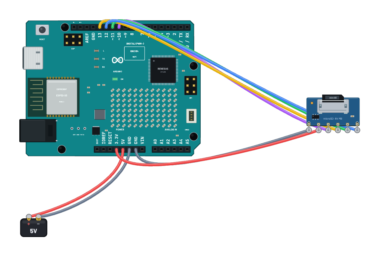 Uno R4 · SPI SD readbackThe pinned MIT SdFat library creates p5.txt on the emulated card, writes breadboard-p5 and reads it back in Serial. D10 selects the card; D11/D12/D13 carry SPI. The card uses the board’s real 3.3 V rail. Recompiling requires SdFat 2.3.0.
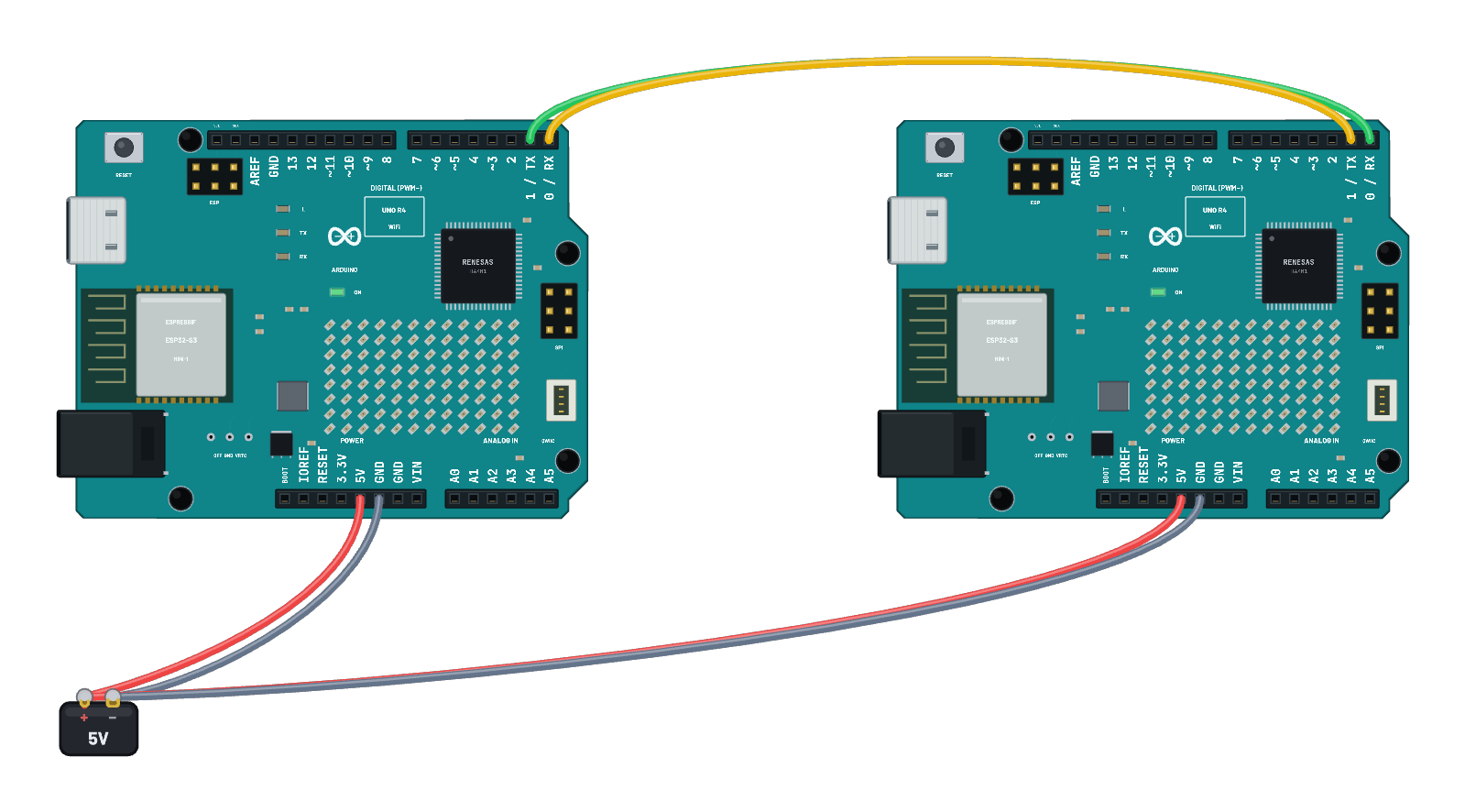 Uno R4 · physical Serial1 peersTwo boards exchange bytes over crossed D1 TX and D0 RX wires at 9600 baud, then 1 Mbaud. Select each board in Serial to read the received decimal values. Reset the simulation to repeat; edit the first board’s sketch in Code.
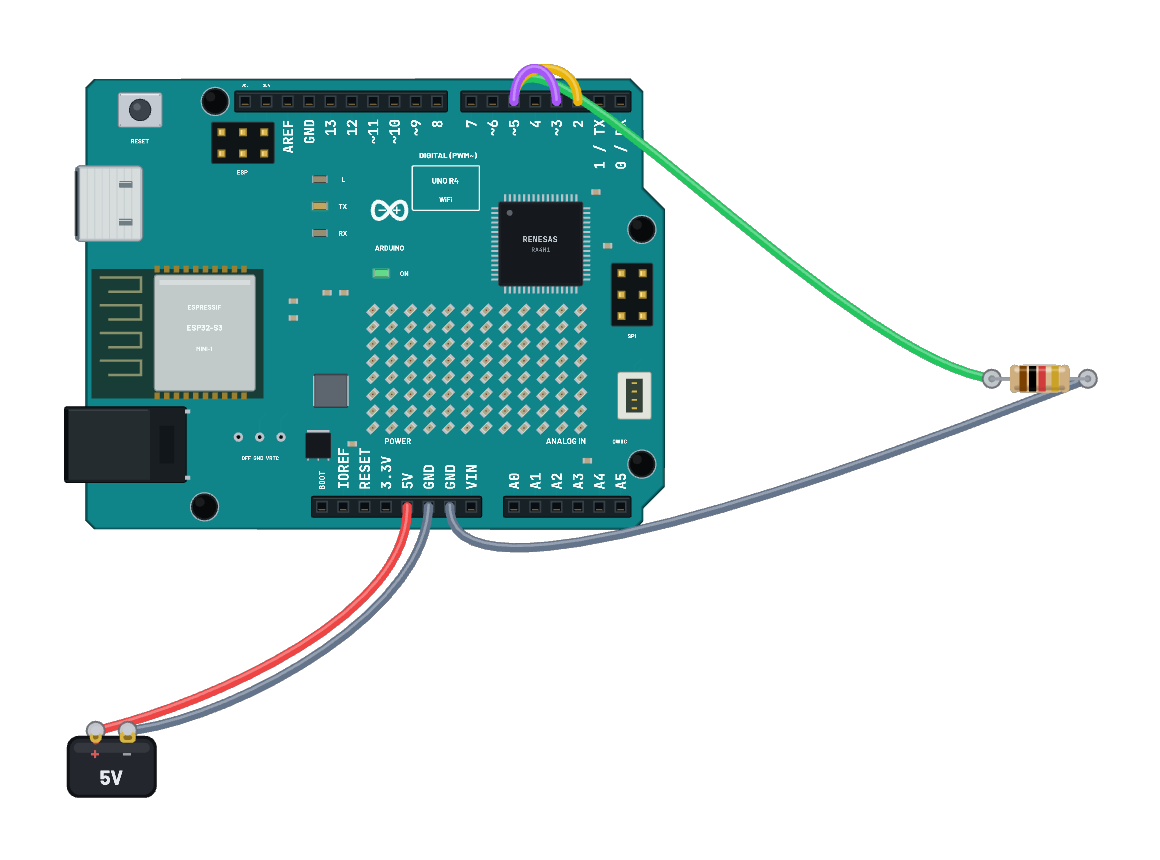 Uno R4 · tone and header interruptsD5 generates a short 1 kHz tone waveform. Physical wires feed D2’s CHANGE interrupt and D3’s FALLING interrupt; Serial prints their edge counts. Probe D5 in Scope and reset the simulation to capture the burst again.
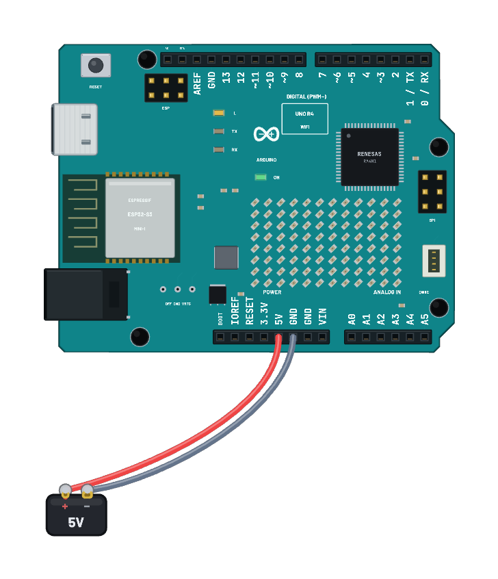 Uno R4 · BlinkThe onboard D13 LED lights for half a second and turns off for half a second. Edit the two delays in Code, or probe D13 in Scope to measure the period.
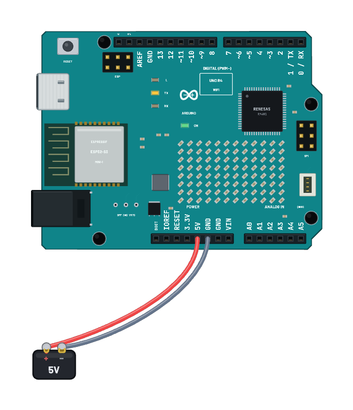 Uno R4 · scan Wi-Fi networksThe official WiFiS3 ScanNetworks sketch lists the simulated networks in Serial every ten seconds. Select the board to change its virtual networks, or open Sniffer to see its real probe requests and responses.
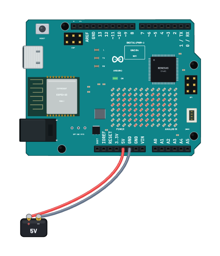 Uno R4 · LED matrix heartThe official Arduino_LED_Matrix library scans a heart through the real 12×8 matrix pins. Edit the bitmap in Code to change the pattern.
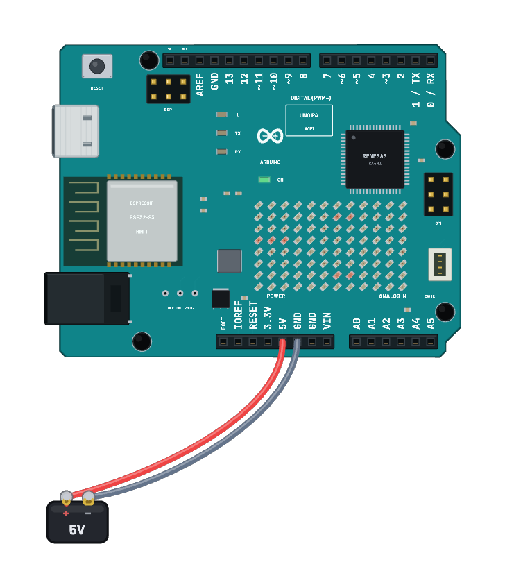 Uno R4 · scrolling matrix textArduinoGraphics scrolls HI across the real 12×8 matrix in 50 ms steps. Edit the text or scroll speed in Code. Recompiling requires the pinned ArduinoGraphics 1.1.5 library.
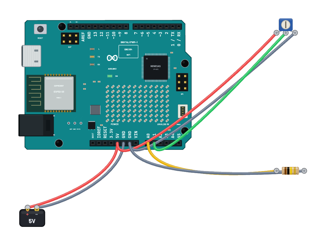 Uno R4 · pot-controlled DAC sineTurn the pot to change the A1 ADC reading and the A0 DAC sine amplitude. Probe A0 in Scope. The real DAC clips near the supply limits; the official core also briefly releases its output between updates.
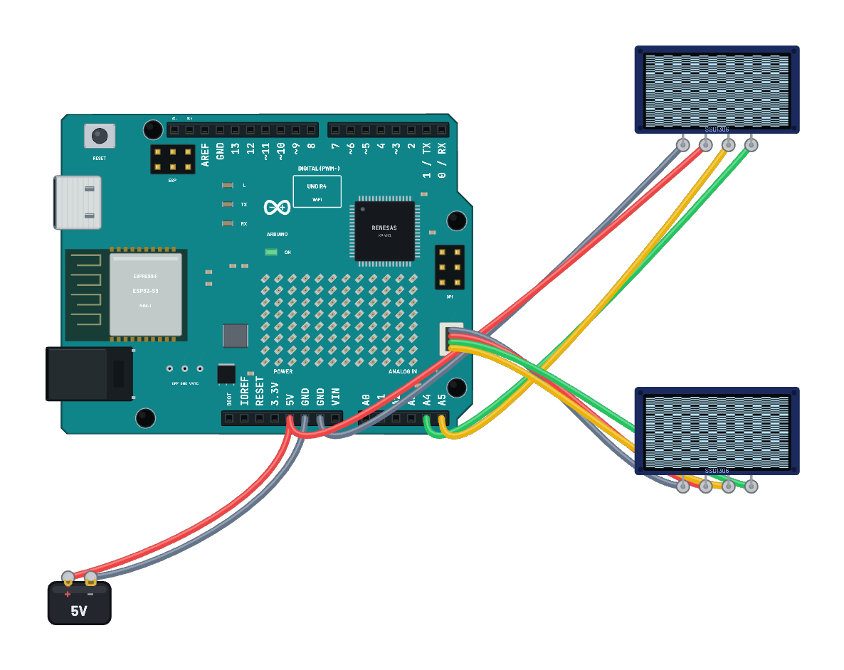 Uno R4 · Wire and Qwiic OLEDsTwo independent official Wire controllers draw complementary patterns. The upper OLED uses the shield SDA/SCL pins; the lower OLED uses all four physical Qwiic contacts, including its switched 3.3 V rail.
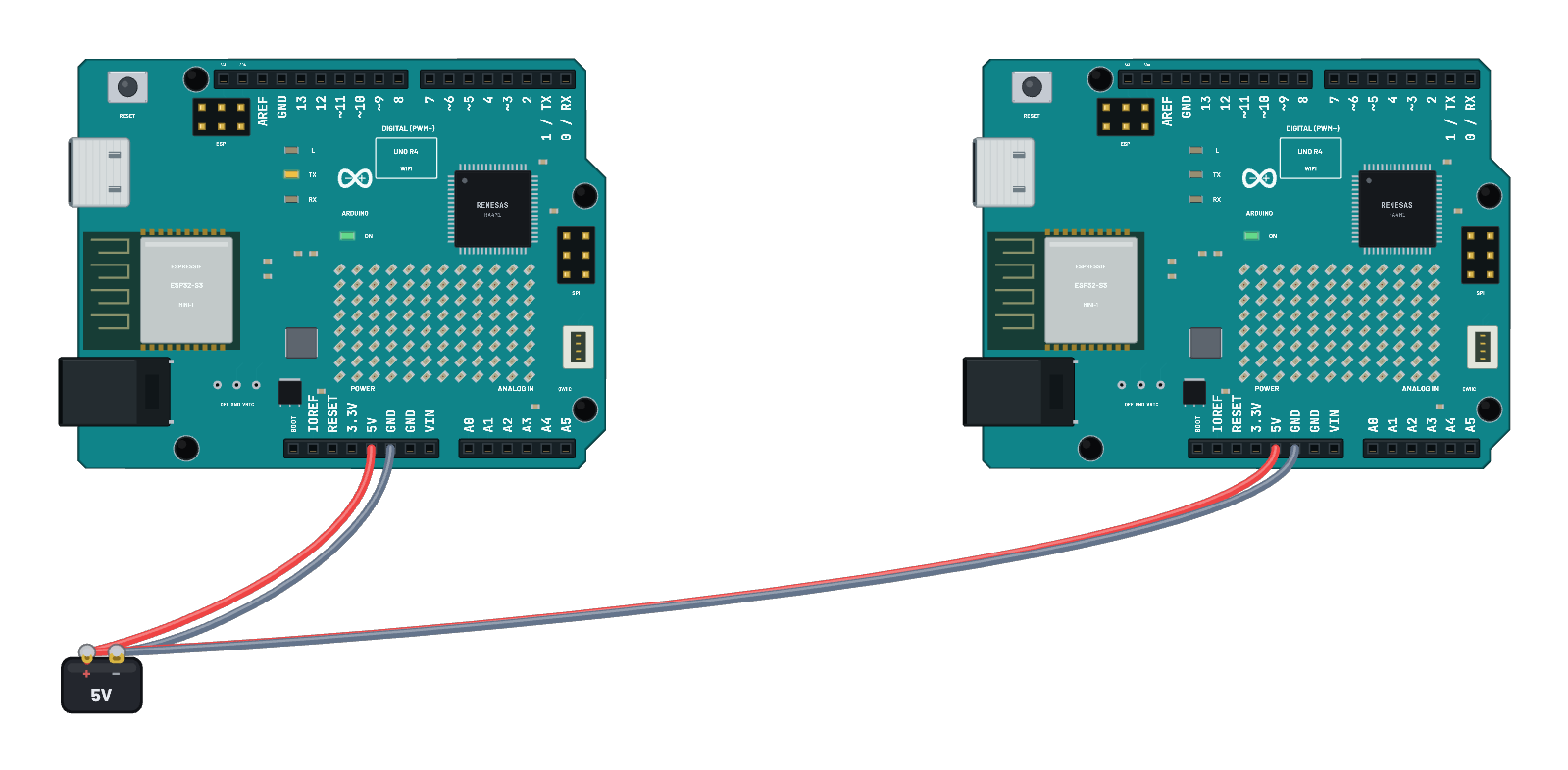 Uno R4 · Wi-Fi access point and HTTP peerThe left board runs the official AP_SimpleWebServer and creates testAP. After its ten-second startup, the right board joins over WPA2 and sends HTTP requests that switch the server’s D13 LED. Edit the client’s requests in Code; inspect the AP’s address and connected station on the left board.
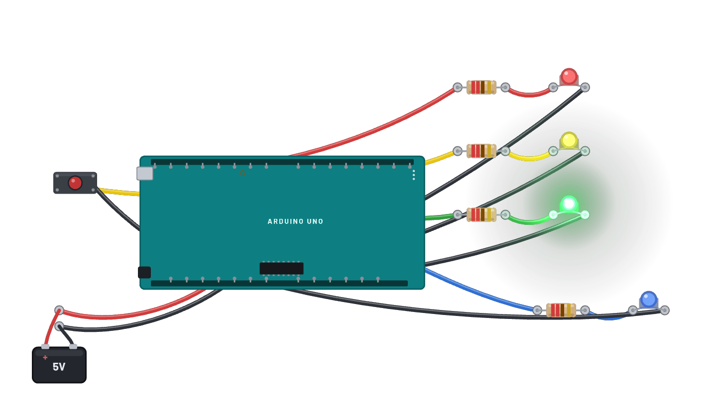 Traffic light + pedestrian crossingA real intersection controller on the Uno: red, yellow and green run the cars while a WALK lamp waits its turn. CLICK AND HOLD THE BUTTON to request a crossing; green yields after its minimum time, yellow bridges, then WALK lights while the cars sit at red and flashes out before green returns. A polled state machine with an input pull-up button, narrated phase by phase on the serial monitor. The Code tab holds the same logic as an editable Arduino sketch.
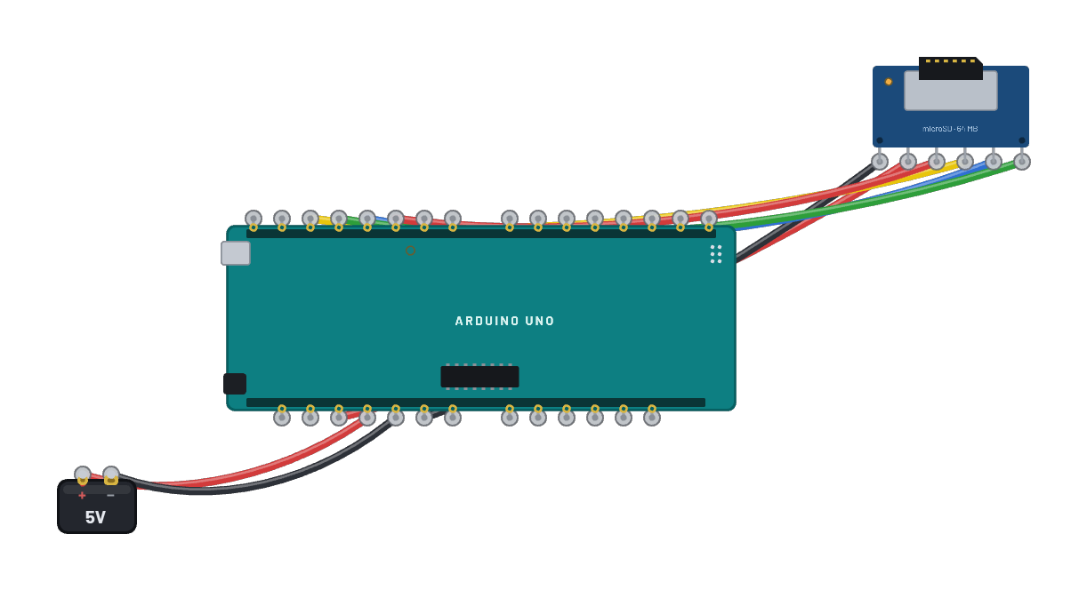 microSD write & read-backA real 64 MB SD card in SPI mode: the Uno runs the honest init handshake (CMD0, CMD8, ACMD41), writes a message into a raw block through the hardware SPI port, reads it back with CMD17 and prints it on the serial monitor — watch the activity LED blink on the breakout. The card ships FAT16-formatted, so the Code tab’s SdFat sketch (compile & upload) can write real files to it too.
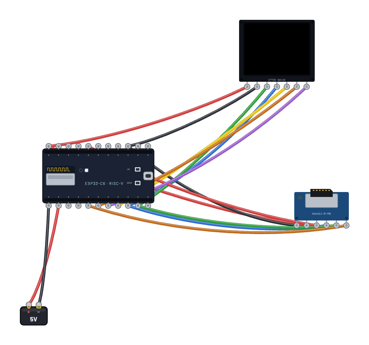 microSD photo frame (TFT slideshow + video)Photos and videos live on the microSD card and stream straight to the ST7735 — both slaves share the ESP32-C6’s hardware SPI bus (`machine.SPI(1)` on the stock pins), each behind its own chip-select. The card ships pre-loaded with three raw `.565` photos (RGB565, zero decode work); the script is also the canonical ~40-line SPI-mode SD driver — CMD0/CMD8/ACMD41 init, CMD18 multi-block reads — mounted with `vfs.VfsFat`. Select the card and open the Inspector’s Card contents panel to put your own images on it — or a video clip / animated GIF via “Add video…”, which converts in your browser to a raw `.565` stream the script plays paced at its own frame rate, exactly like real ST7735 video projects do.
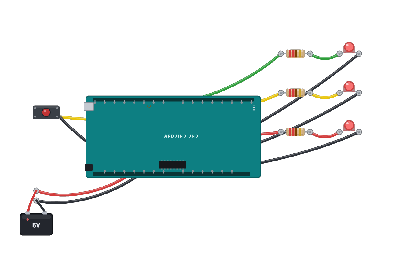 Binary dice rollerCLICK AND HOLD THE BUTTON to spin the die, release to roll: three LEDs show the face 1 to 6 in binary and every roll is announced on the serial monitor. The result is human-timed (whichever face the 50 ms spin lands on when you let go), which is how fairground reaction games actually work. The Code tab holds the same game as an editable Arduino sketch.
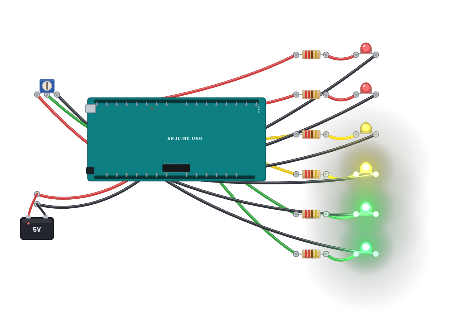 LED bargraph (pot level meter)A VU-meter on the bench: the ATmega328P reads the trim pot with its real 10-bit ADC and lights a six-LED bar on D8-D13, green through red, one LED per ~160 counts. Click the pot and drag its Position slider in the Inspector to sweep the bar up and down; the raw reading prints over serial. The Code tab holds the same meter as an editable Arduino sketch.
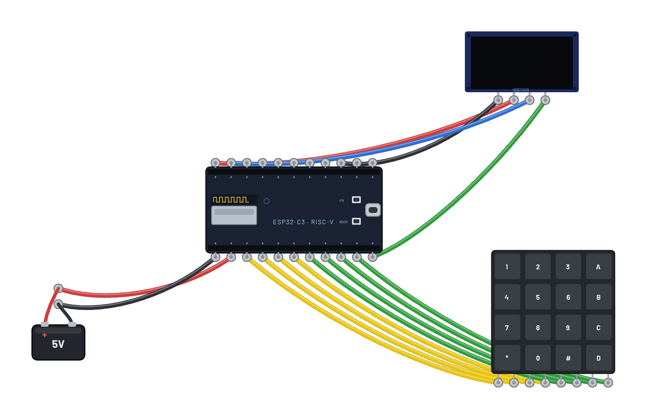 Keypad door lock (keypad + OLED)Click 1 2 3 4 on the keypad, then # to unlock (the OLED prompts you and * clears a mistake). Behind the scenes it is a real embedded project: an ESP32 scans a 4x4 matrix keypad, edge-detects new presses, and drives an OLED lock screen showing UNLOCKED or DENIED — all in MicroPython.
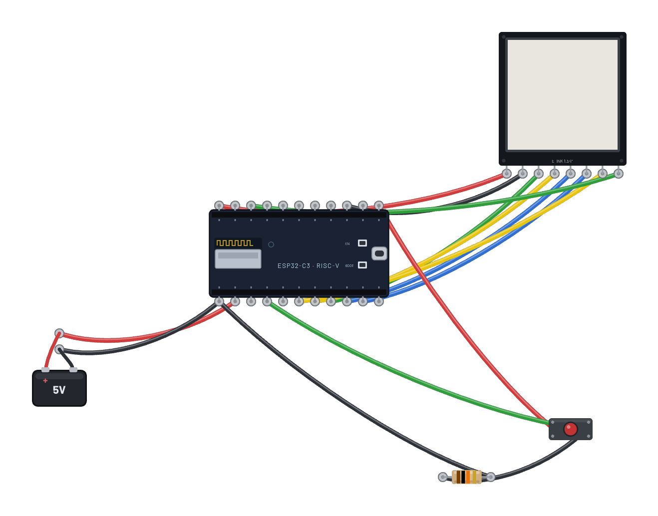 Pocket e-reader (e-ink pages)Three pages of Alice in Wonderland on the 1.54″ e-paper panel, driven over the ESP32-C6’s hardware SPI. Click the button to turn the page; each turn streams 5000 bytes into the SSD1681 RAM and fires a full refresh, flash and all. The current page survives a power cut, exactly like the paperback it is.
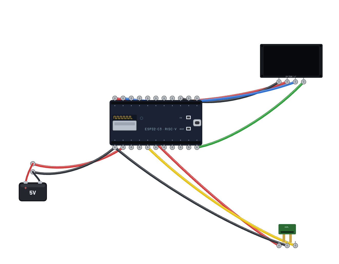 Plant monitor (soil + OLED)A soil-moisture probe on the ADC, its reading shown as a percentage and bar on the SH1106 OLED. Drag the probe’s Moisture slider in the Inspector to water the plant.
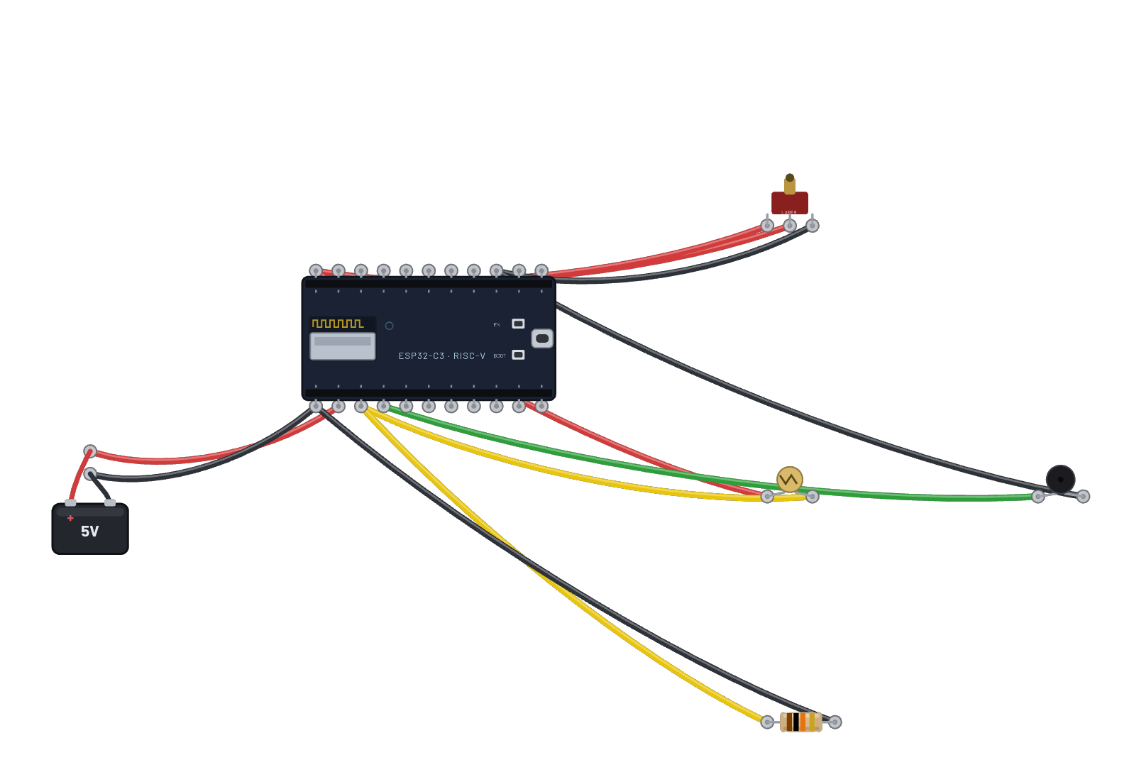 Laser tripwire alarmA laser aimed at a photoresistor; the ESP32 reads the light on its ADC and sounds the buzzer when the beam is broken. Drop the photoresistor’s Light-level slider to break the beam.
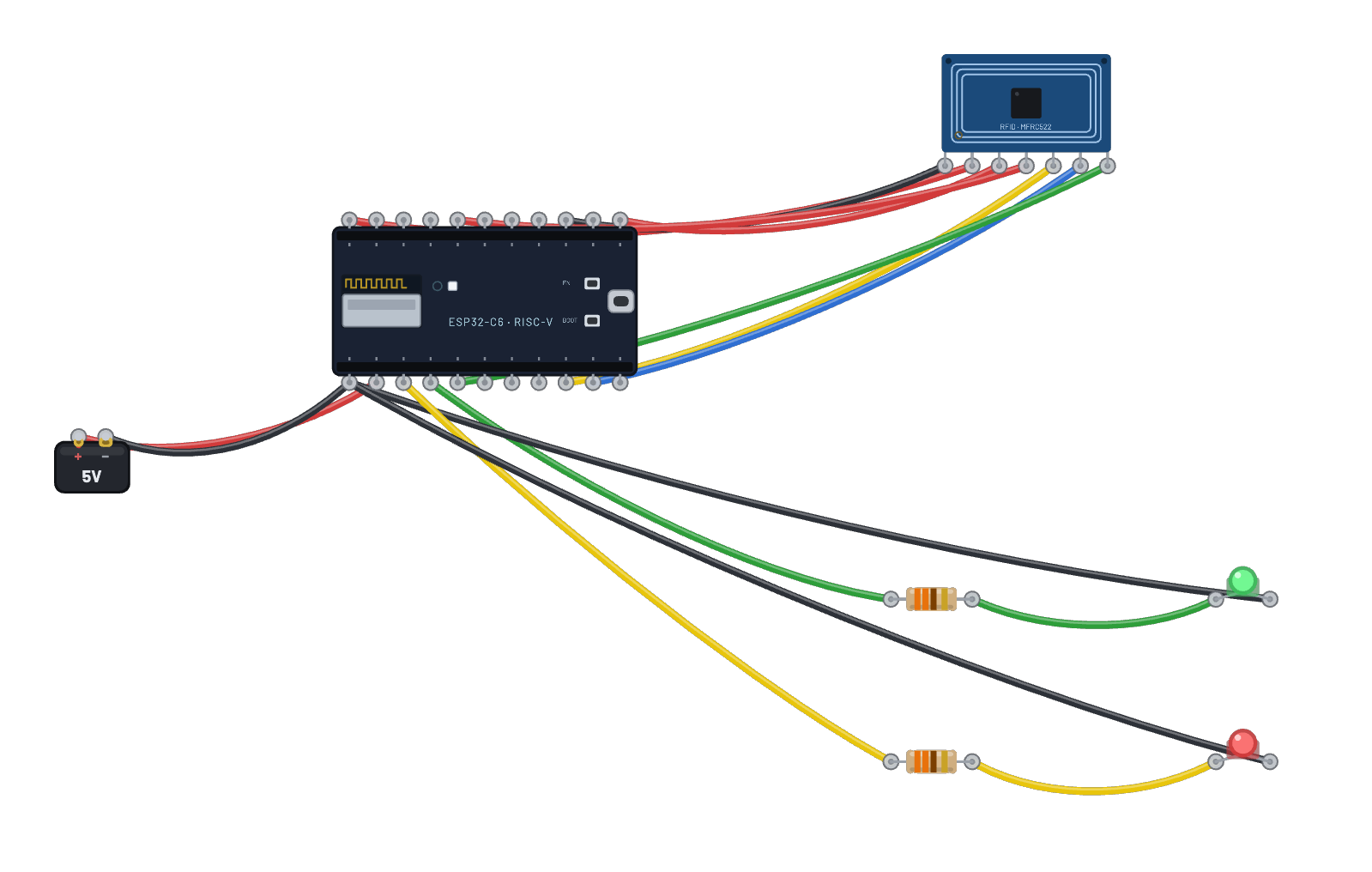 RFID door lockAn MFRC522 reader guarding a two-LED door. Toggle “Hold tag to reader” in the reader’s Inspector: the authorized card lights green and reads a note off block 1; edit the tag UID and tap again to get the red ACCESS DENIED path.
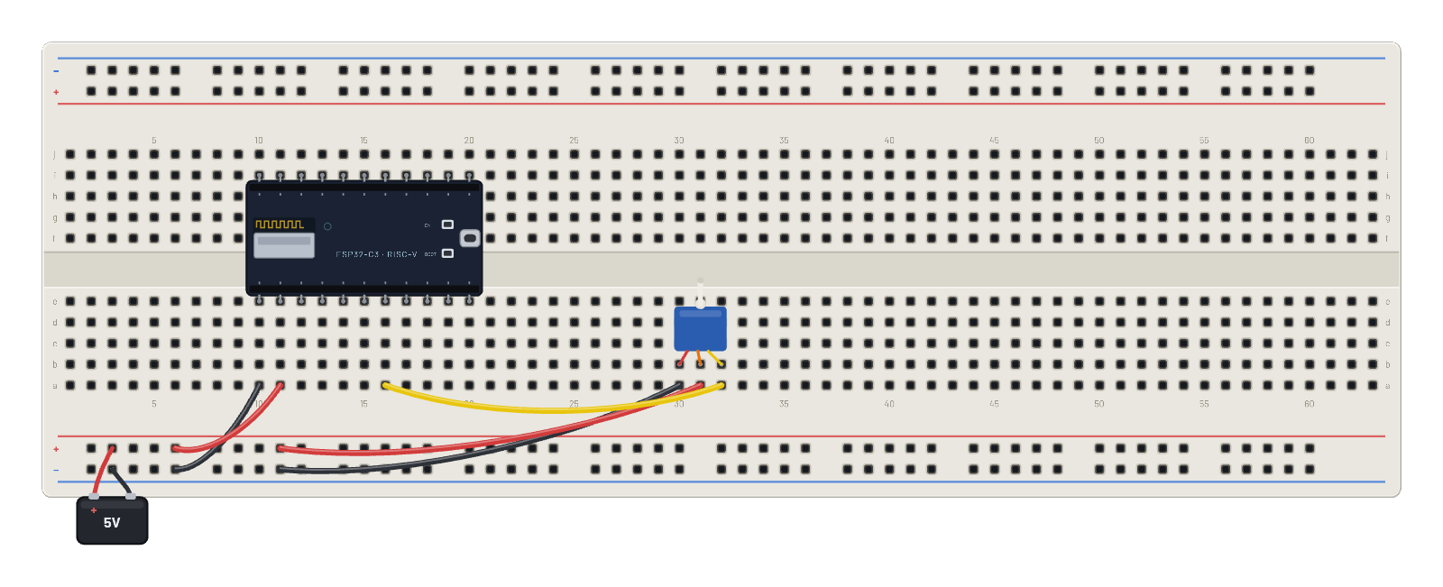 Servo on PWM (LEDC)A servo on G4 driven by the real ESP32 LEDC peripheral. The serial monitor opens with a ready-made sweep script; press ▶ Run script and watch the horn move.
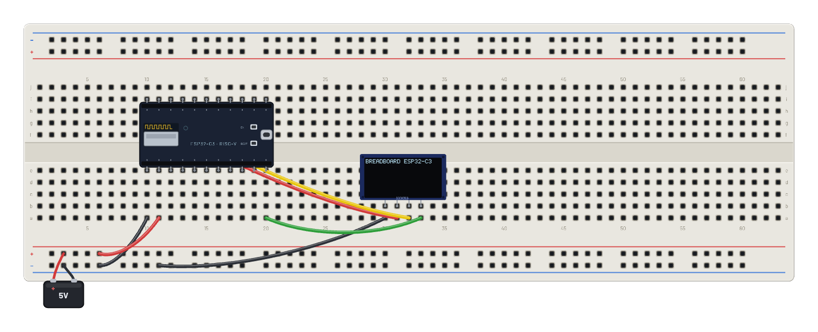 Boot screen on an OLED (no typing)Press Run and watch the ESP32-C3 boot on the screen: CPU check, flash, I2C, the real Wi-Fi radio coming up (with its MAC), a progress bar, then a live uptime/heap status line. Stock ESP-IDF firmware driving the SSD1306 over I2C.
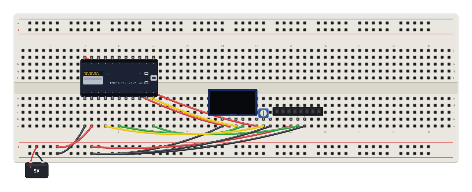 ESP32-S3 peripheral tour (no typing)Fully autonomous: a stock ESP-IDF app on the ESP32-S3 writes the OLED over I2C, animates the NeoPixel strip over RMT, and reads the pot on ADC1. Just press Run.
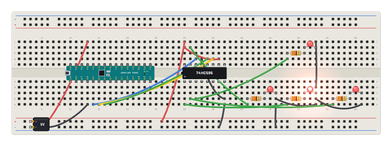 74HC595 binary counterThe Arduino Nano bit-bangs a shift register; four LEDs show the low bits counting up ~10×/second. The Code tab holds the same counter as an editable Arduino sketch.
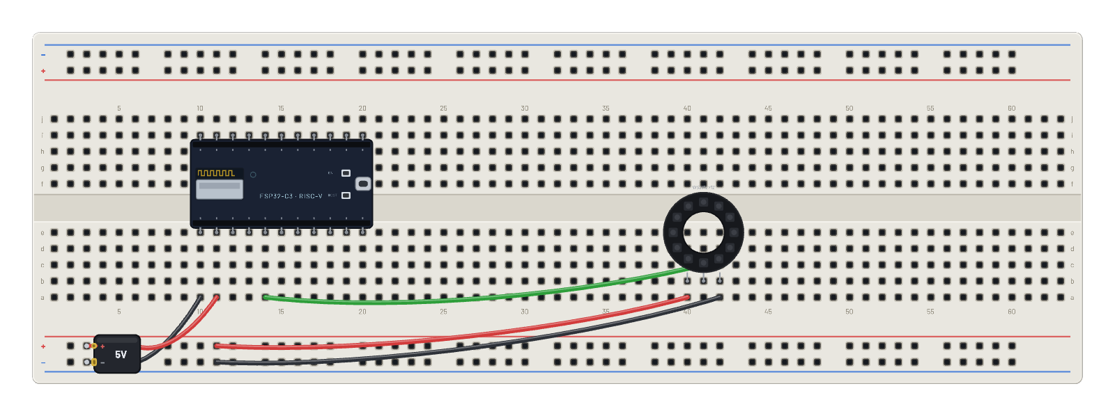 NeoPixel ring rainbowAn ESP32-C3 running real MicroPython chases a rainbow around a 12-pixel WS2812 ring — the genuine 800 kHz protocol, decoded with cycle accuracy. Edit the colors in the Code tab.
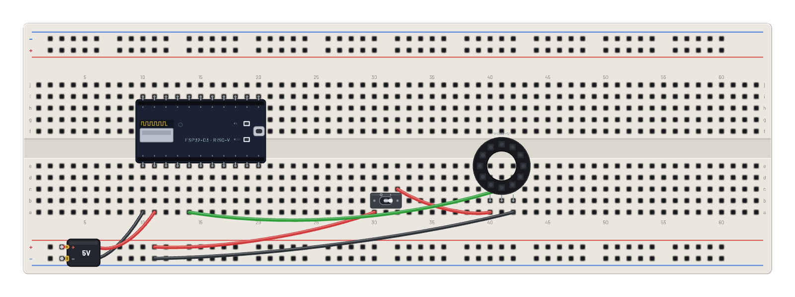 Ring with a power switchThe toggle switch gates the NeoPixel ring's 5 V pin while the ESP32-C3 keeps streaming rainbow frames: flick it off and the ring goes dark instantly; flick it on and the next frame repaints.
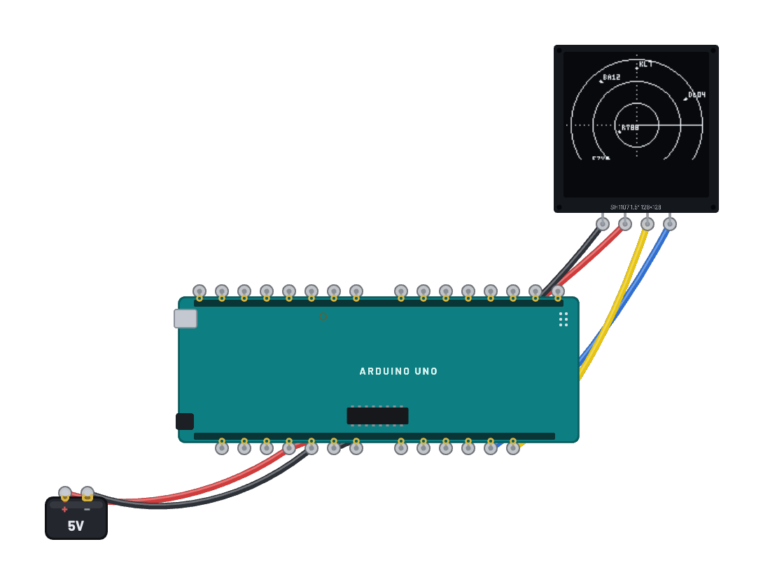 Flight radarA compute-dense radar scope running real compiled Arduino firmware on a 1.5″ 128×128 OLED. A full framebuffer would swallow the Uno's entire 2 KB of SRAM, so the sketch renders the classic embedded way — 16 raster passes per frame into a 128-byte page buffer, each stripe blitted over I²C at 400 kHz — drawing range rings, a rotating sweep and aircraft blips with trails and callsign labels. Watch REAL air traffic: the Flight feed panel opens with this example — pick an airspace and press Start feed to stream live ADS-B aircraft onto the scope. Or feed it yourself over the serial monitor: P,<id>,<x>,<y>,<vx>,<vy>,<label> places or updates an aircraft, R,<id> removes it, and between updates each one dead-reckons along its last heading.
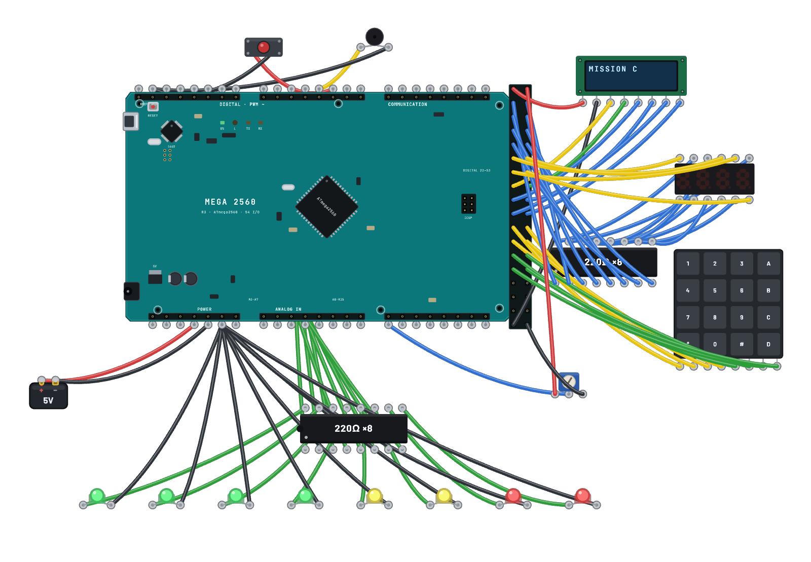 Launch console (Mega 2560)A mission-control panel that needs the Arduino Mega 2560’s ~36 spare GPIO — physically impossible on an Uno. Real compiled Arduino firmware drives a 16×2 LCD, a multiplexed 4-digit countdown display, an 8-LED status bank and a siren. The console stands by until you type 1234 on the keypad — then it narrates a T-minus-10 launch sequence over serial. Twist the fuel-mix pot (read on A8, one of the Mega’s extra ADC channels), and hit the red button to ABORT — wired to d2, which is interrupt INT4 on this chip.
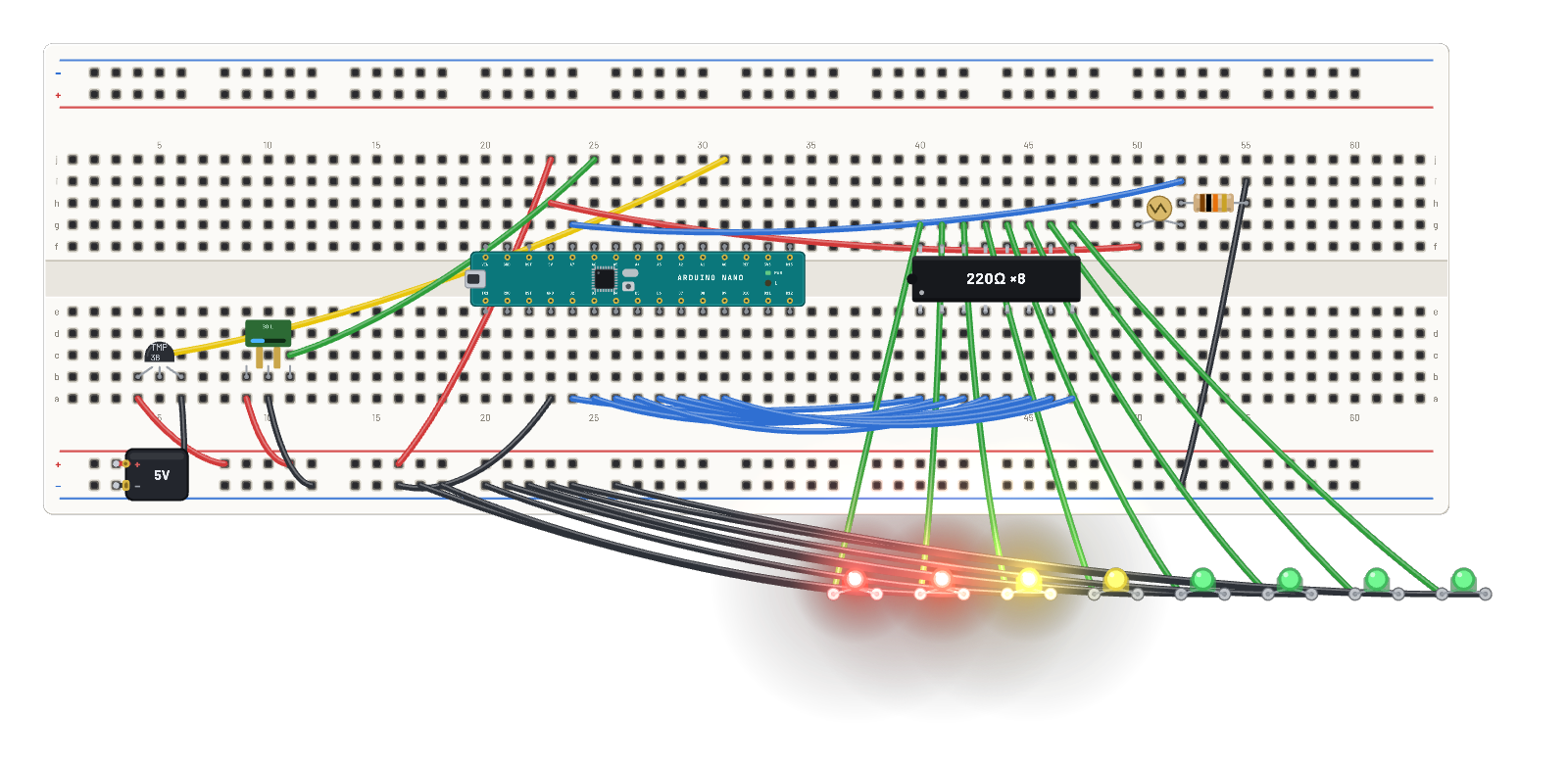 Plant monitor (Nano)A houseplant dashboard built around the Arduino Nano’s special trick: A6 and A7, two analog-only pins the Uno doesn’t have. The soil probe lives on A6 and a photoresistor light divider on A7, so every digital pin stays free for the 8-LED moisture bar on D2–D9 — all eight series resistors packed into one DIP-16 resistor-array. Real compiled Arduino firmware narrates soil, light and temperature (TMP36 on A0) twice a second. Select the soil sensor and drag its moisture slider — the bar and the plant’s mood follow.
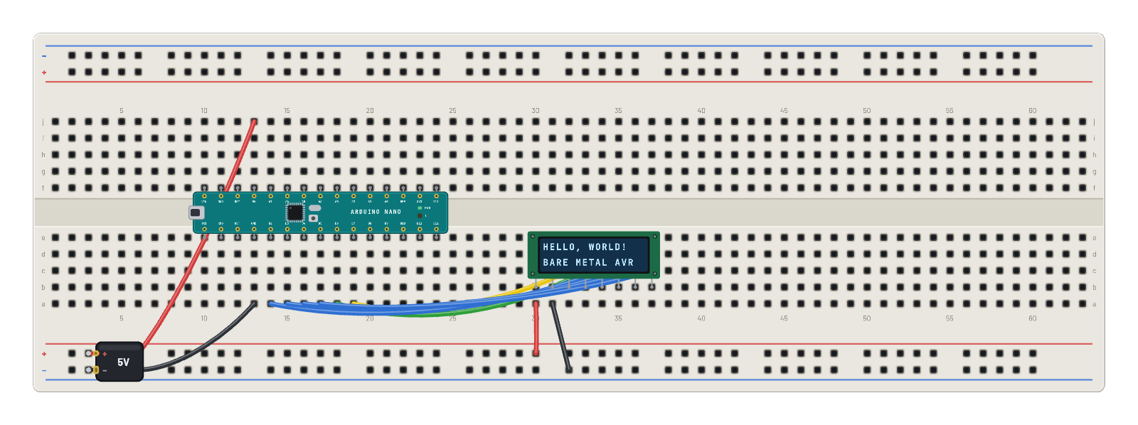 LCD hello worldThe Arduino Nano drives a 16×2 HD44780 character LCD over the real 4-bit protocol: nibbles, E strobes, init dance and all.
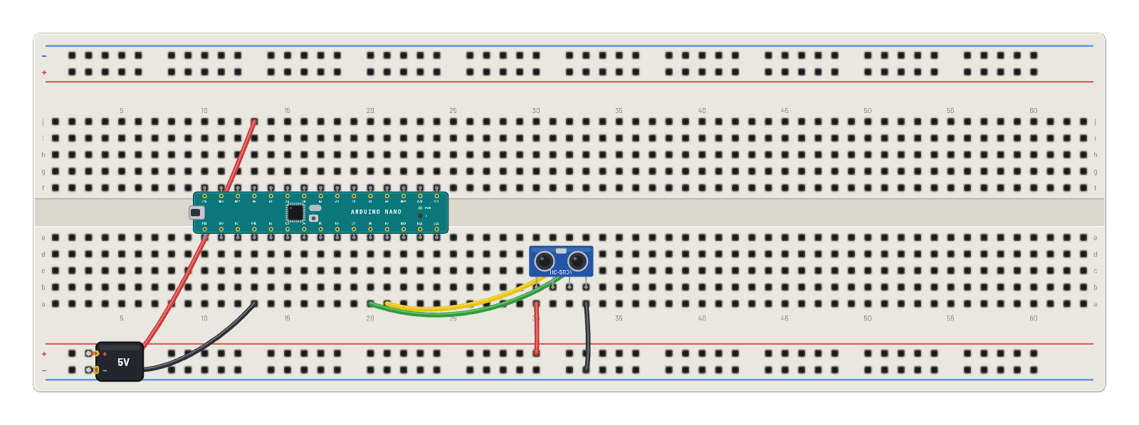 Ultrasonic rulerThe Arduino Nano pings an HC-SR04 and prints the distance over serial. Drag the distance slider and watch the readings follow. The Code tab holds the same ruler as an editable Arduino sketch.
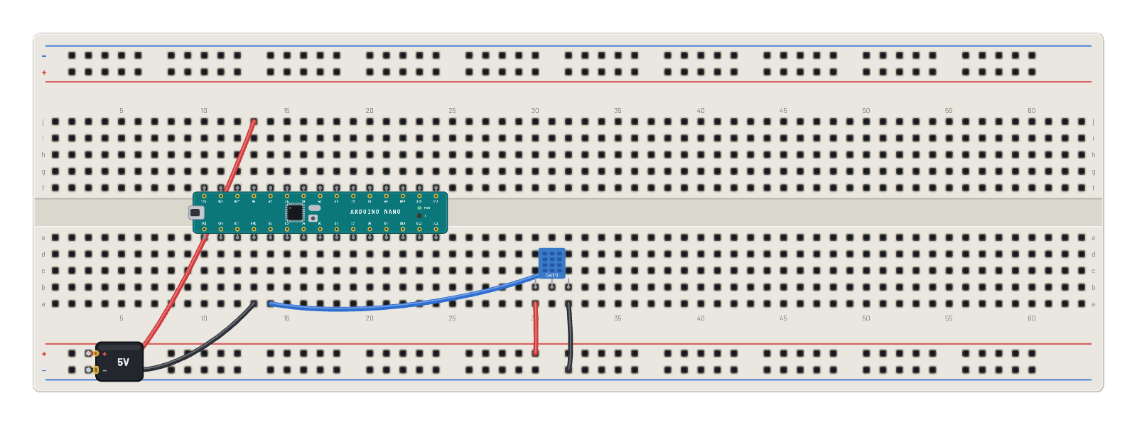 DHT11 climate monitorBare-metal single-wire protocol: the Arduino Nano reads temperature and humidity from a DHT11 and prints them over serial.