Example project · Builds & projects
Servo on PWM (LEDC)
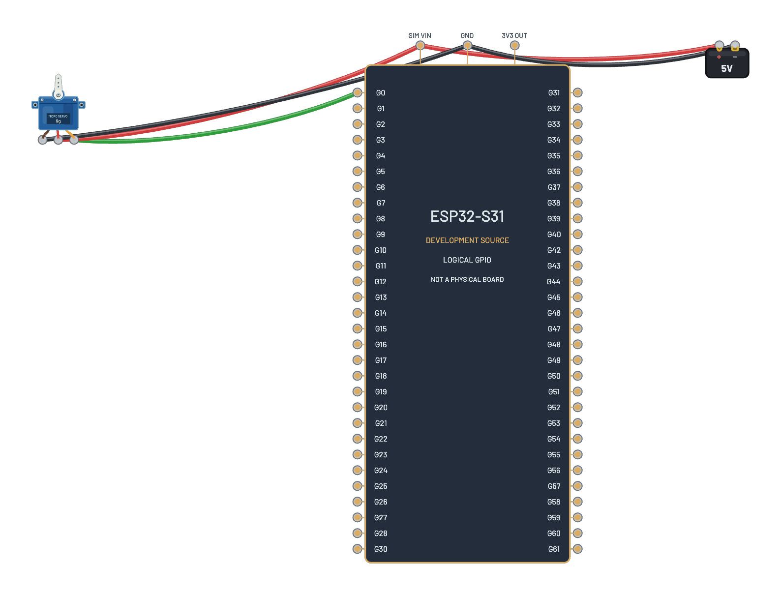
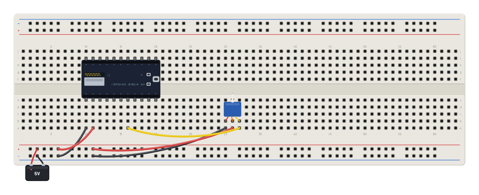
A servo on G4 driven by the real ESP32 LEDC peripheral. The serial monitor opens with a ready-made sweep script; press ▶ Run script and watch the horn move.
How it works
Hobby servo control is just a 50 Hz pulse train whose width picks the angle: 1 ms is 0°, 1.5 ms is 90°, 2 ms is 180°. The script programs the C3's real LEDC peripheral with PWM(Pin(4), freq=50) and walks duty_u16 through 3277, 4915, 6553 (those counts are exactly the 1/1.5/2 ms widths), so the horn sweeps 0° → 90° → 180° → 90° a second apart, then prints 'sweep done' and leaves you at the REPL.
What's on the bench
- Battery
- ESP32-C3
- Servo
How it's wired
- hole a10→hole B-5
- hole a11→hole B+5
- hole a30→hole B-9
- hole a31→hole B+9
- hole a32→hole a16
The code
This MicroPython script runs on the emulated board every boot; edit it in the Code tab.
from machine import Pin, PWM
import time
s = PWM(Pin(4), freq=50)
for us in (3277, 4915, 6553, 4915):  # 0°, 90°, 180°, back
    s.duty_u16(us)
    time.sleep(1)
print("sweep done")
Try this
- After the sweep, type s.duty_u16(6553) at the REPL and send the horn to 180° yourself.
- Probe G4 with the ∿ Scope and measure the pulse width change as you command angles.
- Try duty values between the landmarks: 4096 lands the horn proportionally.
- Note the servo feeds from the 5 V rail: signal is logic, muscle is power.