Burn-out lab
One LED wired right, one wired wrong: watch the wrong one cook. Then press the button to short the rail and blow the fuse.
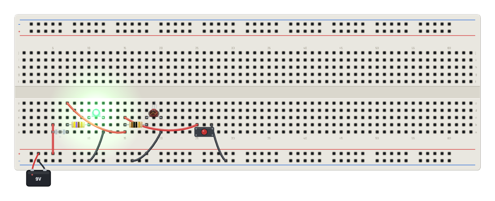
How it works
Two LED branches on a 9 V supply, one designed right and one designed wrong, behind a shared 1 A fuse. The 470 Ω branch runs its green LED at a healthy current forever. The 10 Ω branch slams far past the red LED's ~30 mA continuous rating; burnout is thermal, so it survives a moment before cooking open with a scorch mark and a diagnostic. The big pushbutton is the third lesson: hold it to short the rail, and the sustained over-current heats the fuse until it blows open (i²t, like the real part), killing the whole bench and saving the wiring.
What's on the bench
- 2× LED
- 2× Resistor
- Battery
- Button
- Fuse
How it's wired
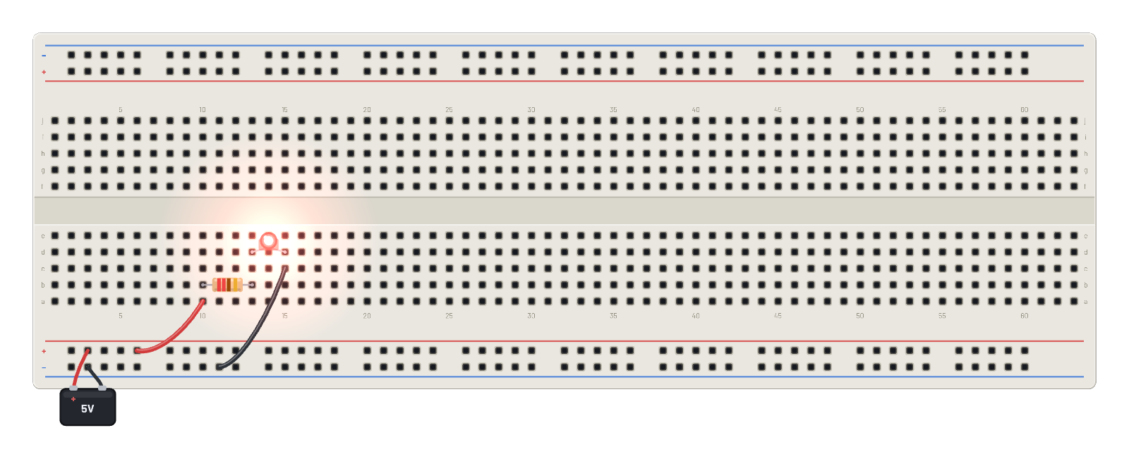
- hole B+4→hole b5
- hole a12→hole B-8
- hole e7→hole a15
- hole a20→hole B-13
- hole b25→hole c15
- hole b27→hole B-24
This project runs prebuilt firmware on the emulated board; open it in the simulator to watch it work and inspect every part live.
Try this
- Watch the first second: the red LED flares, burns open, and gets a scorch mark while the green one just glows.
- Click and hold the button: the short circuit is called out, then the fuse blows and everything goes dark.
- Hover the rail after the fuse blows: 0 V everywhere downstream tells you exactly what died.
- Press ⟲ Restart to fit fresh parts, then fix the design: give the red LED a real resistor.