Example project · Start here
Pi Pico blink
A real emulated RP2040 (Cortex-M0+ at 125 MHz) running bare-metal Thumb assembly: 3.3 V logic blinking an LED on GP2.
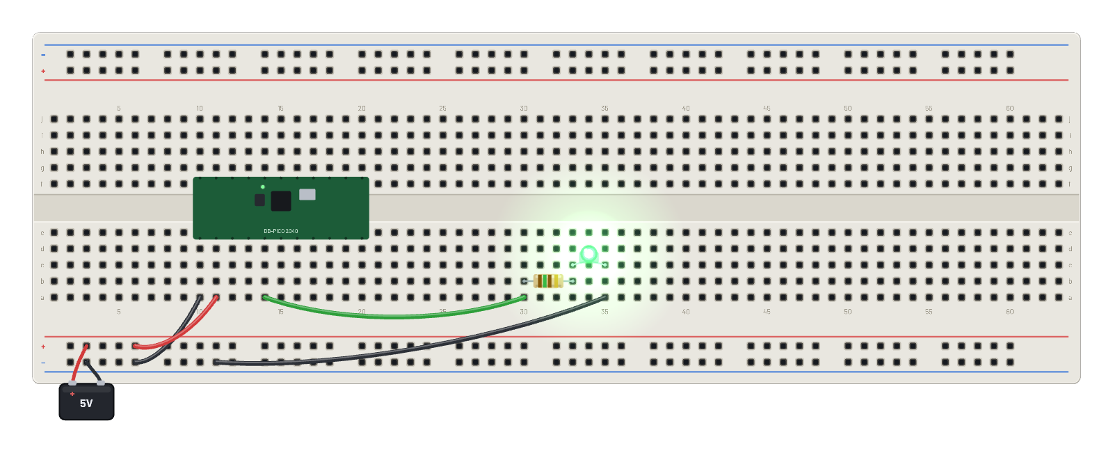
How it works
A real RP2040 (Cortex-M0+ at 125 MHz) booting bare-metal ARM Thumb assembly, no SDK, no framework. The bench feeds 5 V into VSYS and the Pico's onboard regulator makes the 3.3 V rail you can measure on the 3v3 pin. The firmware toggles GP2, and because this is 3.3 V logic the LED needs only a 150 Ω series resistor to hit a sensible current. The blink you see is the emulated core executing the same handful of instructions a real chip would.
What's on the bench
- Battery
- LED
- Pi Pico
- Resistor
How it's wired
- hole a10→hole B-5
- hole a11→hole B+5
- hole a14→hole a30
- hole a35→hole B-9
This project runs prebuilt firmware on the emulated board; open it in the simulator to watch it work and inspect every part live.
Try this
- Hover the 3v3 pin: the onboard regulator really is holding ~3.3 V from the 5 V input.
- Probe GP2 with the ∿ Scope: the square wave tops out at 3.3 V, not 5 V — this is a 3.3 V board.
- Hover VSYS and then a GND pin to trace the power path into the board.
- Undervolt the battery in the Inspector and watch the board brown out and stop blinking.