Example project · Start here
555 LED flasher
The classic NE555 astable blinking an LED at ~1.5 Hz. Probe the cap to watch it ramp.
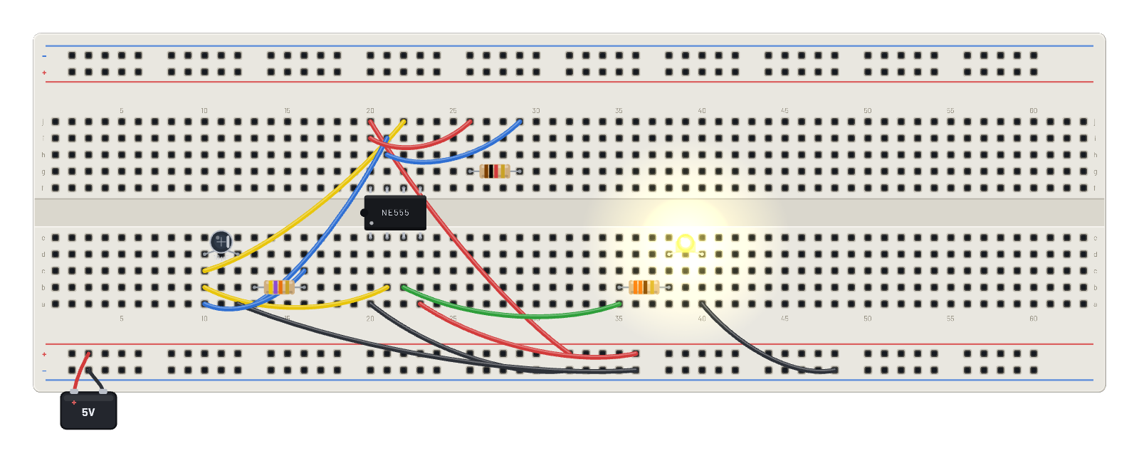
How it works
The classic astable, blinking because the 555's comparators actually compare. The 10 µF capacitor charges through Ra (1 kΩ) + Rb (47 kΩ) toward ⅔ of the 5 V rail; when the THRES comparator trips, the internal flip-flop flips, OUT drops, and DISCH drains the cap back down through Rb to ⅓ Vcc, where TRIG flips everything back. The period is the textbook f = 1.44 / ((Ra + 2·Rb)·C) ≈ 1.5 Hz, and the yellow LED on OUT flashes at exactly that rate.
What's on the bench
- 3× Resistor
- 555 Timer
- Battery
- Capacitor
- LED
How it's wired
- hole j20→hole B+26
- hole a20→hole B-26
- hole a23→hole B+30
- hole b21→hole b10
- hole j22→hole c10
- hole a12→hole B-30
- hole i21→hole a13
- hole c16→hole a10
- hole i20→hole j26
- hole j29→hole h21
- hole b22→hole a35
- hole a40→hole B-40
This project runs prebuilt firmware on the emulated board; open it in the simulator to watch it work and inspect every part live.
Try this
- Probe the capacitor’s top plate and open the ∿ Scope: a sawtooth bouncing between ⅓ and ⅔ of 5 V.
- Put channel 2 on OUT to see the square wave line up with the sawtooth’s turning points.
- Halve Rb to 22 kΩ in the Inspector — the flash rate roughly doubles, exactly as the formula says.
- Swap the cap for 100 µF and watch it slow to a stately once-per-ten-seconds.