Example project · Start here
My first circuit
Battery → resistor → LED. The hello-world of breadboards.
How it works
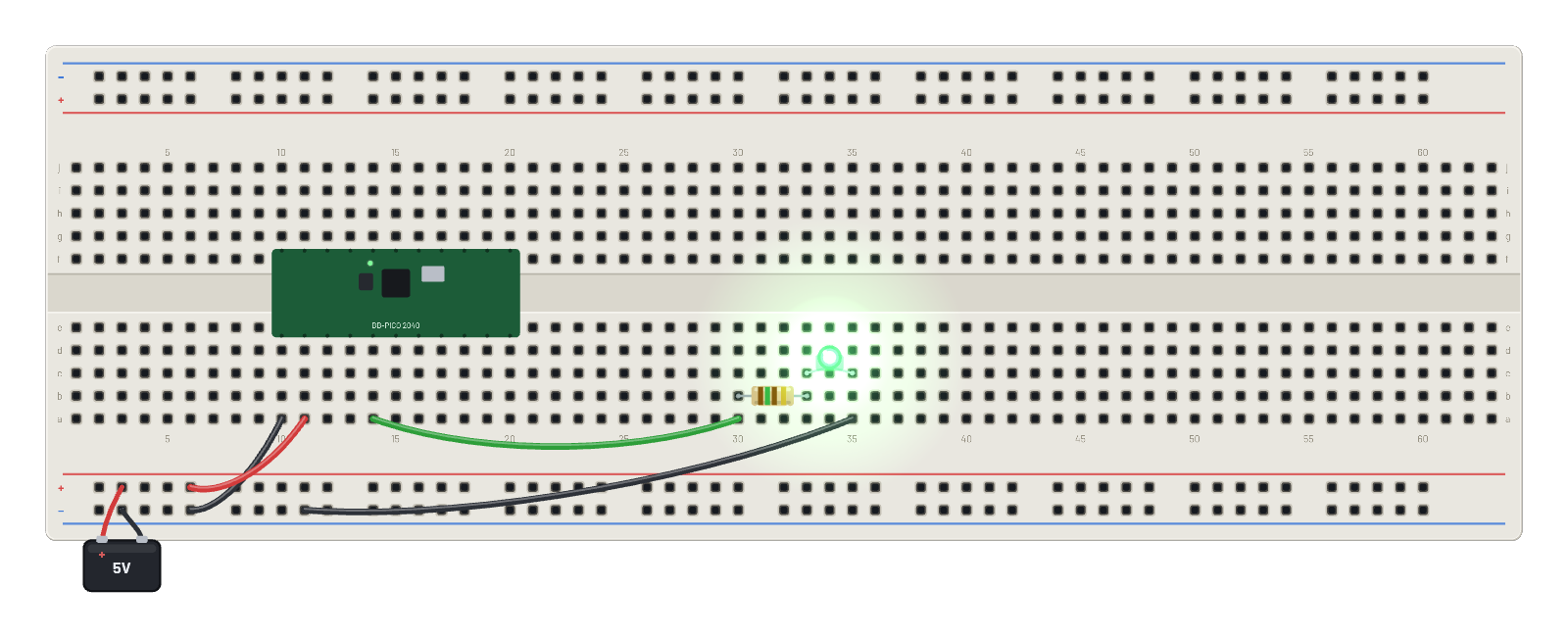
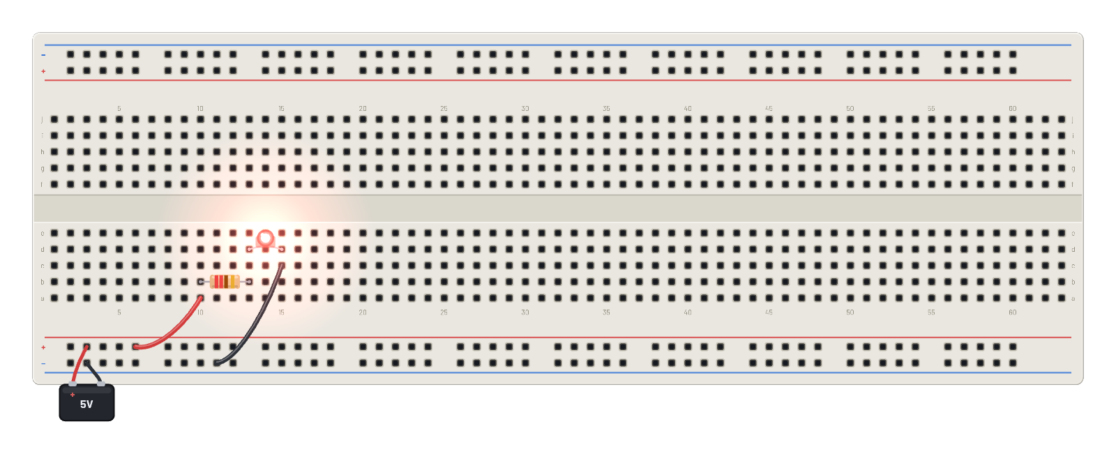
The whole workflow in three parts: a 5 V battery on the rails, a 220 Ω resistor, and a red LED, connected through the breadboard's strips. Current leaves the + rail, drops about 3 V across the resistor, spends ~2 V forward-biasing the LED, and returns to the − rail: roughly 14 mA, comfortably inside the LED's ~30 mA budget, and the solver computes every one of those numbers live. Hover any hole to read the real voltage; the LED's brightness follows the actual current, not an on/off flag.
What's on the bench
- Battery
- LED
- Resistor
How it's wired
- hole B+5→hole a10
- hole c15→hole B-9
This project runs prebuilt firmware on the emulated board; open it in the simulator to watch it work and inspect every part live.
Try this
- Hover the resistor’s two pins: the voltage drop across it is the whole Ohm’s-law lesson.
- Select the resistor and raise its value in the Inspector — 1 kΩ dims the LED, 10 kΩ barely lights it.
- Rotate the LED 180° and watch it go dark: current only flows anode → cathode.
- Drop the resistor to 10 Ω and watch the LED burn out (then press ⟲ Restart for a fresh one).