Example project · Analog & circuits
555 tone generator
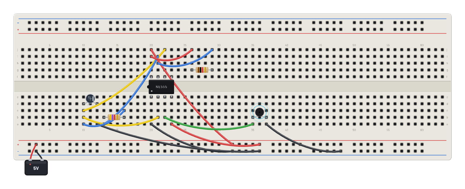
The astable at ~1.4 kHz drives a piezo buzzer. Click 🔊 in the header to actually hear it; change C or Rb to change the pitch.
How it works
The same 555 astable as the LED flasher, tuned three decades faster: Ra = 1 kΩ, Rb = 4.7 kΩ and a 0.1 µF cap give f = 1.44 / ((Ra + 2·Rb)·C) ≈ 1.4 kHz, squarely in the ear's sweet spot. OUT drives a passive piezo buzzer, and a passive buzzer has no voice of its own: it sounds at whatever frequency you feed it, so the pitch is the circuit, not the part.
What's on the bench
- 2× Resistor
- 555 Timer
- Battery
- Buzzer
- Capacitor
How it's wired
- hole j20→hole B+26
- hole a20→hole B-26
- hole a23→hole B+30
- hole b21→hole b10
- hole j22→hole c10
- hole a12→hole B-30
- hole i21→hole a13
- hole c16→hole a10
- hole i20→hole j26
- hole j29→hole h21
- hole b22→hole a35
- hole a37→hole B-40
This project runs prebuilt firmware on the emulated board; open it in the simulator to watch it work and inspect every part live.
Try this
- Click the 🔊 sound button in the header to actually hear the tone.
- Probe OUT and measure the frequency with the ∿ Scope’s automatic measurements.
- Change the cap to 0.047 µF in the Inspector: half the C, about twice the pitch.
- Switch the buzzer's kind to 'active' in the Inspector — now it beeps at its own fixed 2.4 kHz no matter what drives it.