Relay + flyback diode
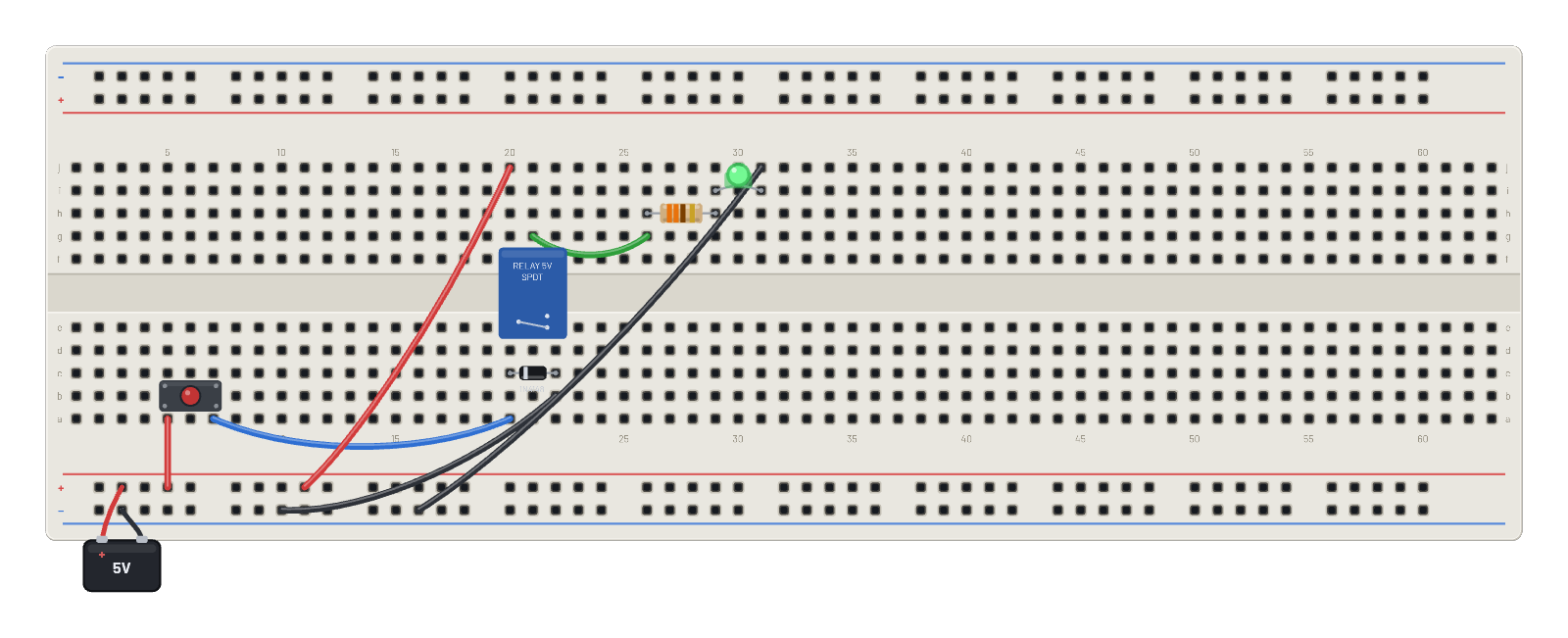
Hold the button to energize the coil; COM swings to NO and lights the LED. The diode across the coil tames the inductive kick.
How it works
An electromagnet throwing a real switch. Holding the pushbutton sends ~45 mA through the relay's ~70 Ω coil; the armature pulls in and the SPDT contacts swing COM over to NO, lighting the LED from a circuit that is electrically separate from the one you pressed. The 1N4148 across the coil (cathode to the driven side) is the flyback diode: when you release, the coil's stored energy has to go somewhere, and the diode gives the collapsing current a safe loop instead of letting the voltage spike.
What's on the bench
- Battery
- Button
- Diode
- LED
- Relay
- Resistor
How it's wired
- hole B+4→hole a5
- hole a7→hole a20
- hole b22→hole B-8
- hole j20→hole B+9
- hole g21→hole g26
- hole j31→hole B-13
This project runs prebuilt firmware on the emulated board; open it in the simulator to watch it work and inspect every part live.
Try this
- Hold the button and watch the relay: coil energized, contacts thrown, LED lit; release and it drops out.
- Probe the driven coil pin, then release the button and catch the clamped kick on the ∿ Scope.
- Delete the flyback diode, scope the same node on release, and meet the spike the diode was absorbing (then undo).
- Rewire the LED branch from NO to NC to invert the logic: lit until you press.