Arduino Uno R3 blink (open bench)
The classic first sketch on the classic board: a real emulated ATmega328P Uno on the open bench, D13 wired to an LED pin-to-pin. The Code tab opens with the sketch; sign in and press Compile & upload to build it on the server and flash the result.
How it works
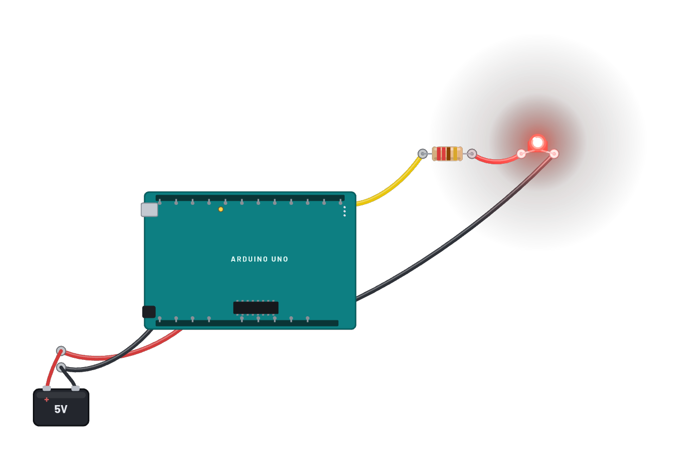
The classic first sketch on the classic board, with no breadboard at all: every part sits free on the bench and wires run pin-to-pin. A 5 V battery feeds the Uno's 5v and gnd pins, and D13 drives the LED through a 220 Ω resistor. The board boots real blink firmware on the emulated ATmega328P, and the Code tab opens with the sketch itself: sign in, edit it, and Compile & upload builds genuine AVR firmware on the server and flashes it here.
What's on the bench
- Arduino Uno R3
- Battery
- LED
- Resistor
How it's wired
- Battery · pos→Arduino Uno R3 · 5v
- Battery · neg→Arduino Uno R3 · gnd
- Arduino Uno R3 · d13→Resistor · a
- Resistor · b→LED · a
- LED · k→Arduino Uno R3 · gnd2
The code
This Arduino C++ sketch lives in the Code tab; sign in and press Compile & upload to build real firmware for the emulated board.
// The classic blink. Edit it, then Compile & upload (sign-in needed):
// the server builds real AVR firmware and boots it on this emulated Uno.
void setup() {
  pinMode(LED_BUILTIN, OUTPUT);
}

void loop() {
  digitalWrite(LED_BUILTIN, HIGH);
  delay(500);
  digitalWrite(LED_BUILTIN, LOW);
  delay(500);
}
Try this
- Drag the parts around: free placement means the wires follow, and the circuit keeps running.
- Hover the d13 pin and watch it alternate between ~5 V and 0 V every half second.
- Edit the delays in the Code tab and press Compile & upload (sign-in needed) to run your own build.
- Add a second LED + resistor from d12 to gnd, copy the pattern in the sketch, and make them alternate.