Boot screen on an OLED (no typing)
Press Run and watch the ESP32-C3 boot on the screen: CPU check, flash, I2C, the real Wi-Fi radio coming up (with its MAC), a progress bar, then a live uptime/heap status line. Stock ESP-IDF firmware driving the SSD1306 over I2C.
How it works
A stock ESP-IDF app (not MicroPython) compiled for the C3 and booted through the real Espressif boot ROM: no typing, it just runs. The firmware drives the SSD1306 over I²C and narrates a boot sequence like a little appliance would: CPU check, flash, I²C probe, then it brings the actual Wi-Fi radio up and prints its real MAC, fills a progress bar, and settles into a live status line with uptime and free heap ticking.
What's on the bench
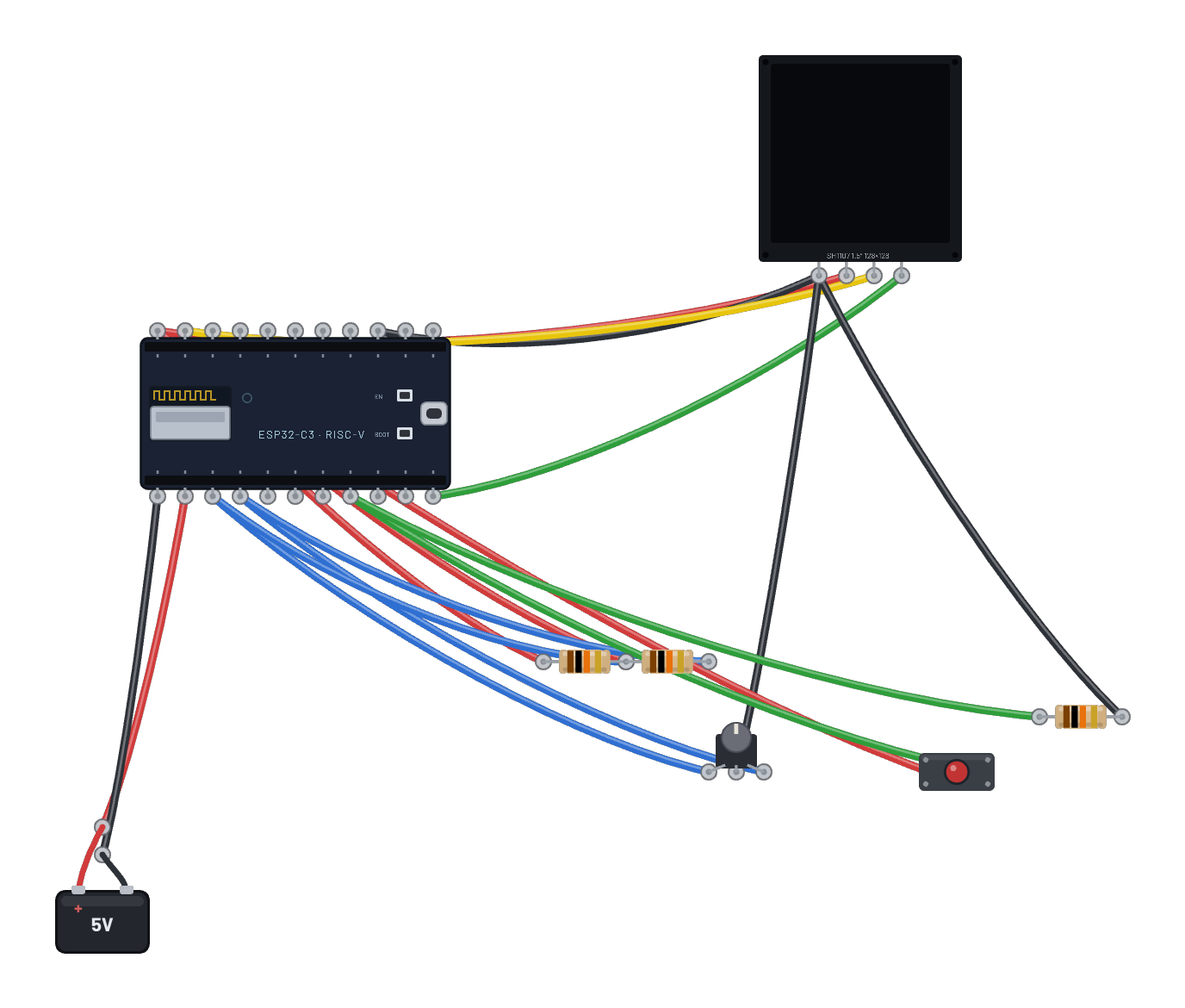
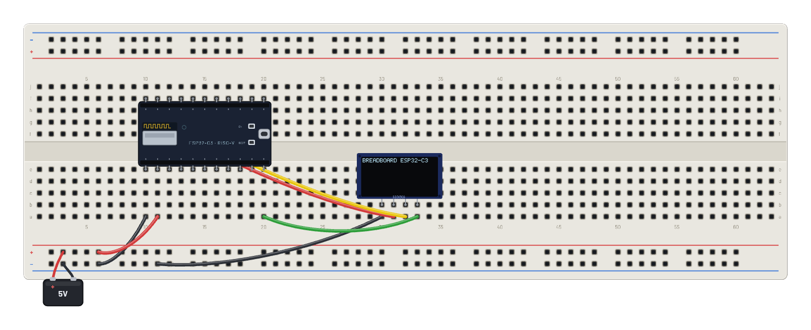
- Battery
- ESP32-C3
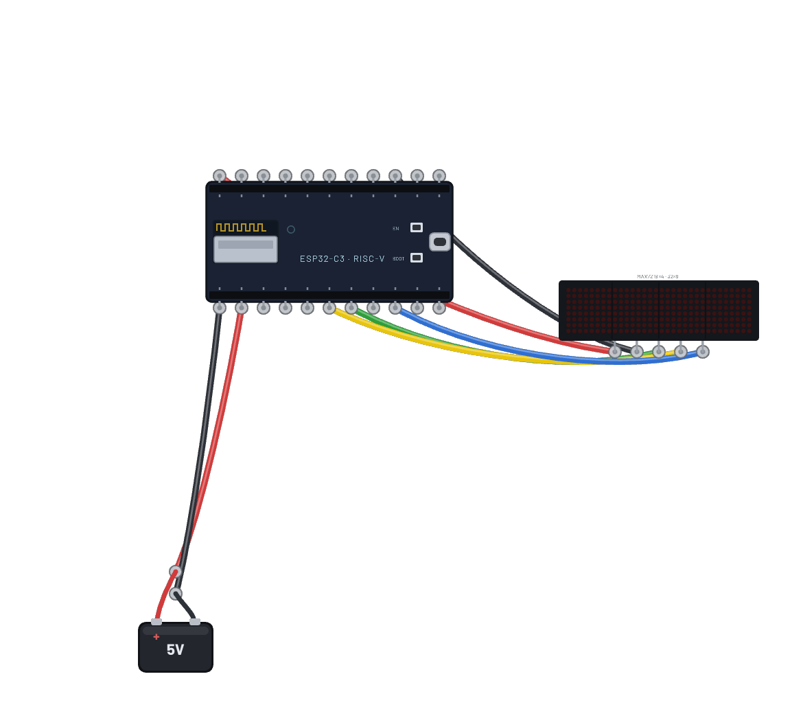
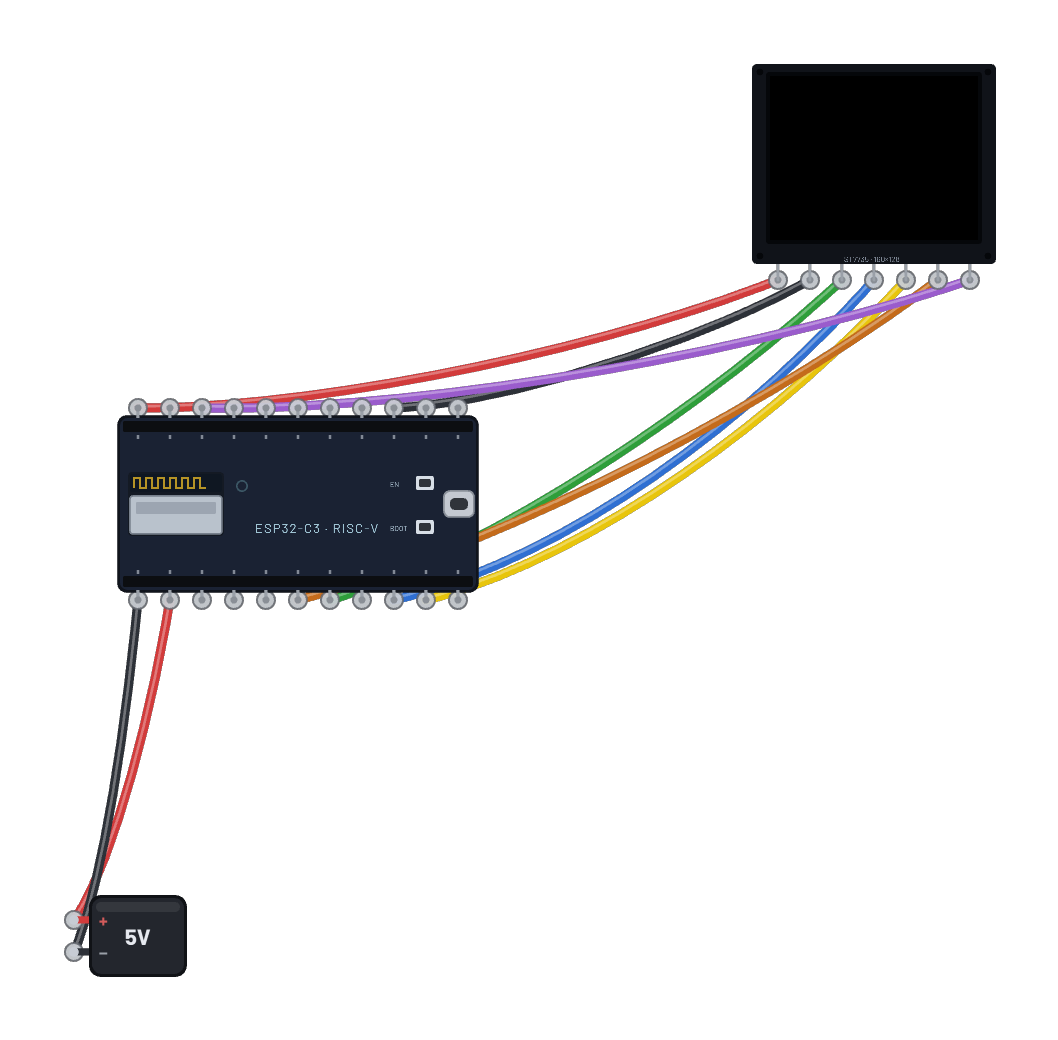
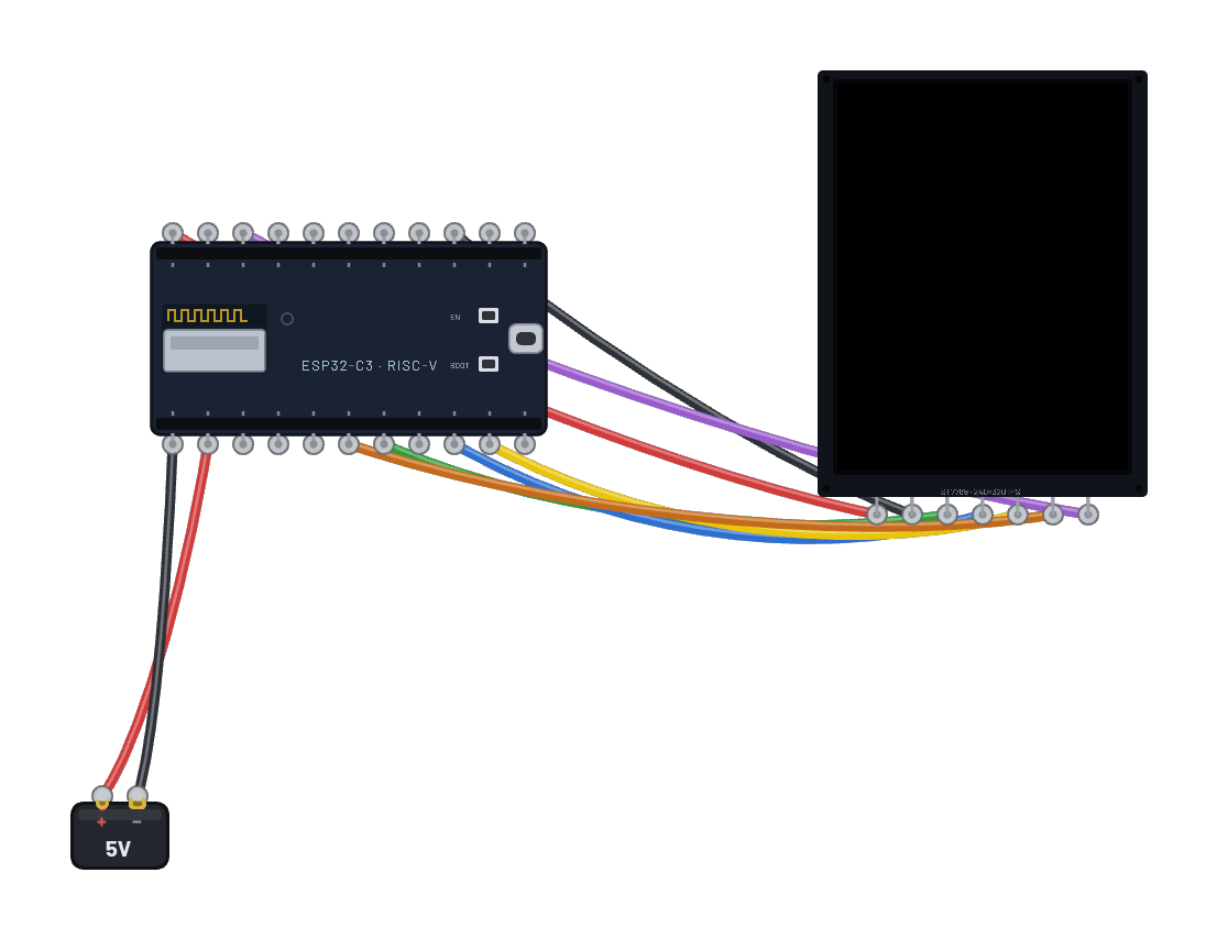
- OLED 128×64
How it's wired
- hole a10→hole B-5
- hole a11→hole B+5
- hole a30→hole B-9
- hole a31→hole h10
- hole a32→hole h11
- hole a33→hole a20
This project runs prebuilt firmware on the emulated board; open it in the simulator to watch it work and inspect every part live.
Try this
- Watch the progress bar fill as each subsystem reports in.
- Open the Serial panel for the firmware's own boot log (CPU: RISC-V x1 OK … WIFI: UP).
- Press ⟲ Restart to replay the whole boot from the ROM up.
- Select the ESP32-C3 and check the Inspector: the radio the firmware brought up is really on.