Example project · Start here
ESP32 blink
A real emulated ESP32-C3 (RISC-V RV32IMC at 160 MHz, Rust→WASM) booting genuine MicroPython and blinking the LED on G2. The blink code lives in the Code tab; edit it and run it again.
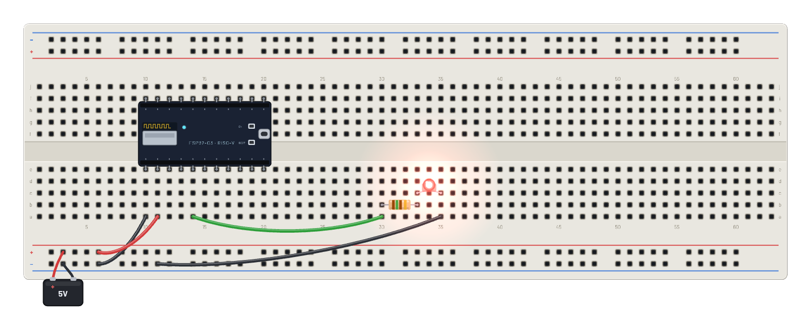
How it works
The ESP32-C3 boots an unmodified MicroPython 1.28 image through the genuine Espressif boot ROM: the banner in the Serial panel is the real firmware talking. The Code tab's script then runs automatically: Pin(2, Pin.OUT) toggles G2 every 250 ms for 500 cycles, printing as it goes, and the LED follows through its 150 Ω resistor (3.3 V logic). When the script finishes you're left at a live REPL prompt you can type at.
What's on the bench
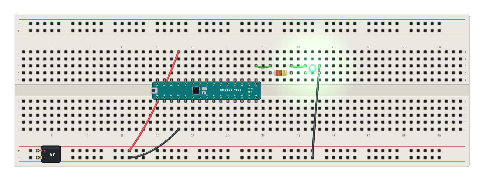
- Battery
- ESP32-C3
- LED
- Resistor
How it's wired
- hole a10→hole B-5
- hole a11→hole B+5
- hole a14→hole a30
- hole a35→hole B-9
The code
This MicroPython script runs on the emulated board every boot; edit it in the Code tab.
from machine import Pin
import time
print('blinking G2 from MicroPython')
led = Pin(2, Pin.OUT)
for n in range(500):
    led.value(n % 2)
    time.sleep_ms(250)
print('blink done')
Try this
- Open the Serial panel and wait for 'blink done', then type led.value(1) at the >>> prompt yourself.
- Change sleep_ms(250) in the Code tab and press Run on board — the script re-runs through the REPL.
- Press ⟲ Restart: the boot banner replays and the script starts again on boot, like flashed firmware.
- Probe G2 and watch the 3.3 V square wave on the ∿ Scope.