How it works
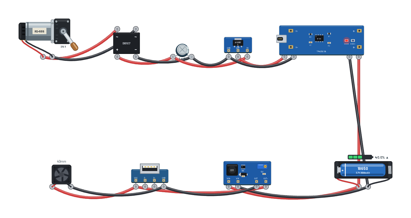
The whole energy chain of a crank-charged power bank. The generator is a DC motor turned by hand: its voltage rises with the crank speed and sags under load. A DB107 bridge rectifies it, so either crank direction works, and a 1000 µF capacitor smooths it. An AMS1117-5.0 makes the 5 V a TP4056 charger needs; the TP4056 charges the 18650 at up to about 0.9 A, then holds 4.2 V and stops. An MT3608 boost converter turns the cell's 3–4.2 V back into 5 V on the USB-A socket, where a 40 mm fan stands in for whatever you plug in. The cell's charge is integrated from the real current every step.
What's on the bench
- 18650 Li-ion Cell
- 40mm Fan (5V)
- AMS1117 Reg
- Bridge Rectifier
- Capacitor
- Hand-crank Generator
- MT3608 Boost
- TP4056 Charger
- USB-A Socket
How it's wired
- Hand-crank Generator · pos→Bridge Rectifier · ac1
- Hand-crank Generator · neg→Bridge Rectifier · ac2
- Bridge Rectifier · pos→Capacitor · a
- Bridge Rectifier · neg→Capacitor · b
- Capacitor · a→AMS1117 Reg · in
- Capacitor · b→AMS1117 Reg · gnd
- AMS1117 Reg · out→TP4056 Charger · inp
- AMS1117 Reg · gnd→TP4056 Charger · inn
- TP4056 Charger · batp→18650 Li-ion Cell · pos
- TP4056 Charger · batn→18650 Li-ion Cell · neg
- 18650 Li-ion Cell · pos→MT3608 Boost · vinp
- 18650 Li-ion Cell · neg→MT3608 Boost · vinn
- MT3608 Boost · voutp→USB-A Socket · vbus
- MT3608 Boost · voutn→USB-A Socket · gnd
- USB-A Socket · vbus→40mm Fan (5V) · pos
- USB-A Socket · gnd→40mm Fan (5V) · neg
This project runs prebuilt firmware on the emulated board; open it in the simulator to watch it work and inspect every part live.
Try this
- Select the cell: its charge climbs while the red CHRG LED is lit.
- Select the generator and slow the crank below about 3600 rpm: the regulator drops out, the TP4056 stops, and the cell runs the fan alone.
- Crank backwards (a negative speed): the bridge still delivers the right polarity.
- Set the cell to 100 %: the charger finishes, the blue STDBY LED lights, and the fan keeps turning.