Zigbee door sensor + smart button
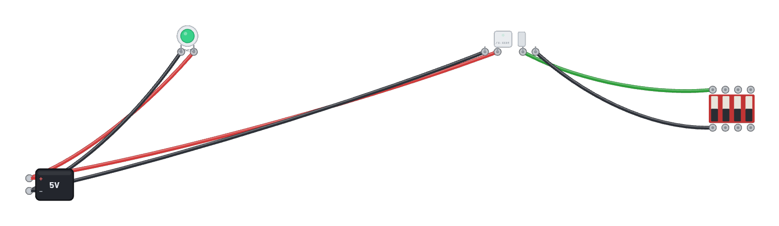
A door/window sensor as a sealed product: the C6 inside runs esp-zigbee IAS-zone firmware, and the smart-button puck (the coordinator) forms the network it joins. The DIP switch across the contact terminals plays the door: flip it and the sensor reports a genuine zone-status change over the air (watch its serial tab and the 📡 Sniffer). Click the sensor for its live join + contact state.
How it works
A wired door sensor is just a contact and a radio — and that’s exactly what this is. The sealed C6 inside runs esp-zigbee IAS-zone contact firmware: its GPIO4 input (with the internal pull-up) reads the two contact terminals, and the smart-button puck is the coordinator whose network it joins. The DIP switch across the terminals plays the door: closed = terminals shorted = contact made. Every change calls setClosed()/setOpen() in the firmware, which reports a genuine IAS zone-status change over the air.
What's on the bench
- Battery
- DIP Switch
- Zigbee Contact Sensor
- Zigbee Smart Button
How it's wired
- Battery · pos→Zigbee Smart Button · vcc
- Battery · neg→Zigbee Smart Button · gnd
- Battery · pos→Zigbee Contact Sensor · vcc
- Battery · neg→Zigbee Contact Sensor · gnd
- Zigbee Contact Sensor · c1→DIP Switch · a0
- Zigbee Contact Sensor · c2→DIP Switch · b0
The code
The exact Arduino C++ sketch(es) the bundled firmware was compiled from — shown in the simulator’s Code tab, where you can edit them and press Compile & upload to rebuild the board’s firmware.
// Zigbee contact sensor (door/window) — an IAS Zone end device.
//
// The contact input is GPIO4 with the internal pull-up: short it to GND
// (door CLOSED) or leave it open (door OPEN), exactly like the two screw
// terminals on a wired door-sensor. Every change reports a genuine IAS
// zone-status change to the coordinator over the air.

#include <Arduino.h>
#ifndef ZIGBEE_MODE_ED
#error "Zigbee end device mode is not selected in Tools->Zigbee mode"
#endif

#include "Zigbee.h"

#define ZIGBEE_CONTACT_ENDPOINT 10
const uint8_t contact = 4;  // GPIO4: LOW (shorted to GND) = closed

ZigbeeContactSwitch zbContact = ZigbeeContactSwitch(ZIGBEE_CONTACT_ENDPOINT);

void setup() {
  Serial.begin(115200);
  pinMode(contact, INPUT_PULLUP);

  zbContact.setManufacturerAndModel("Breadboard", "DoorSensor");
  Serial.println("Adding ZigbeeContactSwitch endpoint to Zigbee Core");
  Zigbee.addEndpoint(&zbContact);

  if (!Zigbee.begin()) {
    Serial.println("Zigbee failed to start!");
    Serial.println("Rebooting...");
    ESP.restart();
  }
  Serial.println("Connecting to network");
  while (!Zigbee.connected()) {
    Serial.print(".");
    delay(100);
  }
  Serial.println();
  Serial.println("Joined. Contact reports armed (GPIO4: low = closed).");
}

void loop() {
  static int last = -1;
  int level = digitalRead(contact);
  if (level != last) {
    last = level;
    if (level == LOW) {
      zbContact.setClosed();
      Serial.println("DOOR CLOSED (contact made) - reported");
    } else {
      zbContact.setOpen();
      Serial.println("DOOR OPEN (contact broken) - reported");
    }
  }
  delay(100);
}
Firmware licence
Notice: this firmware uses the LGPL-licensed Arduino core library
arduino-zigbee-switch-c6.bin is statically linked with Arduino-ESP32 3.3.10. Parts of this library are licensed under the GNU Lesser General Public License, version 2.1 or (at your option) any later version. You may modify this work for your own use and reverse engineer it to debug those modifications. Download the relink package and corresponding source to rebuild it with a changed library.
It also links Espressif’s ZBOSS Zigbee stack, supplied unchanged under its own licence, which forbids reverse engineering, decompiling, modifying or disassembling the ZBOSS binary itself. Relink with the ZBOSS archives unchanged.
- Relink package: zigbee-switch-c6-relink.zip (1.0 MB)
- Required shared inputs: arduino-esp32-3.3.10-esp32c6-sdk.zip (10.0 MB), arduino-esp32-3.3.10-notices.zip (0.1 MB)
- Corresponding source: arduino-esp32-3.3.10-core-source.zip (1.2 MB), arduino-esp32-3.3.10-esp32c6-headers-source.zip (2.1 MB)
- Licence texts and relink instructions
Notice: this firmware uses the LGPL-licensed Arduino core library
arduino-zigbee-contact-c6.bin is statically linked with Arduino-ESP32 3.3.10. Parts of this library are licensed under the GNU Lesser General Public License, version 2.1 or (at your option) any later version. You may modify this work for your own use and reverse engineer it to debug those modifications. Download the relink package and corresponding source to rebuild it with a changed library.
It also links Espressif’s ZBOSS Zigbee stack, supplied unchanged under its own licence, which forbids reverse engineering, decompiling, modifying or disassembling the ZBOSS binary itself. Relink with the ZBOSS archives unchanged.
- Relink package: zigbee-contact-c6-relink.zip (1.0 MB)
- Required shared inputs: arduino-esp32-3.3.10-esp32c6-sdk.zip (10.0 MB), arduino-esp32-3.3.10-notices.zip (0.1 MB)
- Corresponding source: arduino-esp32-3.3.10-core-source.zip (1.2 MB), arduino-esp32-3.3.10-esp32c6-headers-source.zip (2.1 MB)
- Licence texts and relink instructions
Try this
- Wait for the sensor to join (its serial tab prints the dots, then "Joined").
- Flip DIP switch 0 and watch DOOR OPEN / DOOR CLOSED print as each report transmits.
- Click the sensor: the Inspector shows its live join state and contact position (the magnet bar slides).
- Open the 📡 Sniffer to catch the IAS zone report frames.