Zigbee smart button + bulb
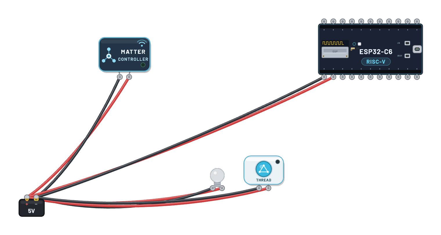
Two sealed products, no DevKit: a wireless smart button and the bulb it controls, each a real emulated ESP32-C6. The button puck is the coordinator: it forms the network, the bulb joins and binds, and then CLICK AND HOLD THE PUCK briefly: a real ZCL Toggle crosses the 802.15.4 air and the glass lights. Click the bulb for its live join state, and follow the join and toggle in the 📡 Sniffer. (The join takes a moment.)
How it works
Two sealed products, two real emulated ESP32-C6 chips, no DevKit. The button puck runs the esp-zigbee coordinator (switch) firmware: it forms the network and opens it for joining. The bulb hides its own C6 running esp-zigbee light firmware; it scans, joins, and binds to the coordinator over the shared 802.15.4 air. Clicking the puck presses its internal BOOT pin — the firmware’s GPIO interrupt fires and sends a real ZCL Toggle to the bound bulb, whose on/off callback drives the internal WS2812 that the glass renders.
What's on the bench
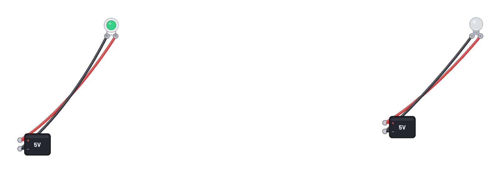
- 2× Battery
- Zigbee Bulb
- Zigbee Smart Button
How it's wired
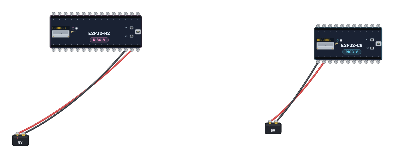
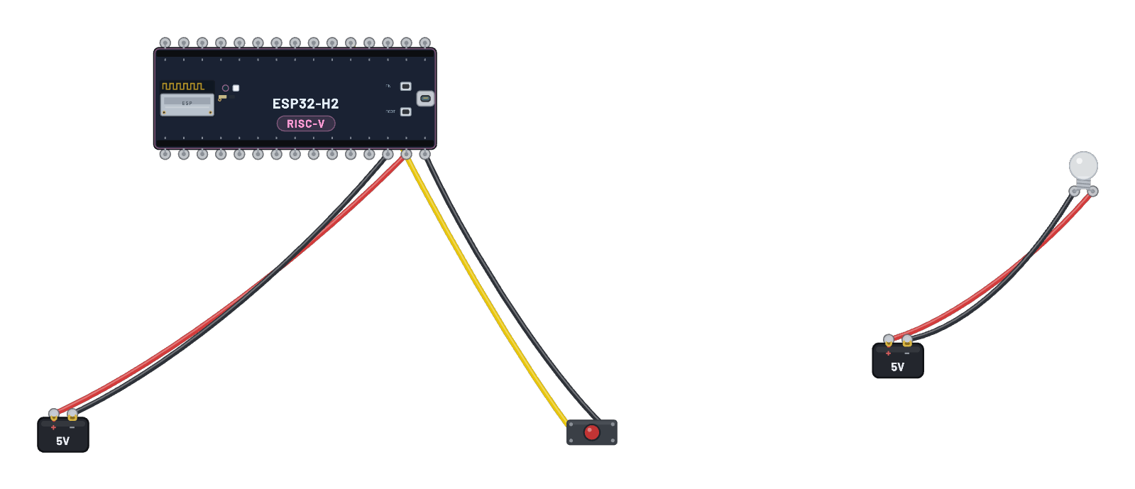
- Battery · pos→Zigbee Smart Button · vcc
- Battery · neg→Zigbee Smart Button · gnd
- Battery · pos→Zigbee Bulb · vcc
- Battery · neg→Zigbee Bulb · gnd
This project runs prebuilt firmware on the emulated board; open it in the simulator to watch it work and inspect every part live.
Firmware licence
Notice: this firmware uses the LGPL-licensed Arduino core library
arduino-zigbee-switch-c6.bin is statically linked with Arduino-ESP32 3.3.10. Parts of this library are licensed under the GNU Lesser General Public License, version 2.1 or (at your option) any later version. You may modify this work for your own use and reverse engineer it to debug those modifications. Download the relink package and corresponding source to rebuild it with a changed library.
It also links Espressif’s ZBOSS Zigbee stack, supplied unchanged under its own licence, which forbids reverse engineering, decompiling, modifying or disassembling the ZBOSS binary itself. Relink with the ZBOSS archives unchanged.
- Relink package: zigbee-switch-c6-relink.zip (1.0 MB)
- Required shared inputs: arduino-esp32-3.3.10-esp32c6-sdk.zip (10.0 MB), arduino-esp32-3.3.10-notices.zip (0.1 MB)
- Corresponding source: arduino-esp32-3.3.10-core-source.zip (1.2 MB), arduino-esp32-3.3.10-esp32c6-headers-source.zip (2.1 MB)
- Licence texts and relink instructions
Notice: this firmware uses the LGPL-licensed Arduino core library
arduino-zigbee-light-c6.bin is statically linked with Arduino-ESP32 3.3.10. Parts of this library are licensed under the GNU Lesser General Public License, version 2.1 or (at your option) any later version. You may modify this work for your own use and reverse engineer it to debug those modifications. Download the relink package and corresponding source to rebuild it with a changed library.
It also links Espressif’s ZBOSS Zigbee stack, supplied unchanged under its own licence, which forbids reverse engineering, decompiling, modifying or disassembling the ZBOSS binary itself. Relink with the ZBOSS archives unchanged.
- Relink package: zigbee-light-c6-relink.zip (1.0 MB)
- Required shared inputs: arduino-esp32-3.3.10-esp32c6-sdk.zip (10.0 MB), arduino-esp32-3.3.10-notices.zip (0.1 MB)
- Corresponding source: arduino-esp32-3.3.10-core-source.zip (1.2 MB), arduino-esp32-3.3.10-esp32c6-headers-source.zip (2.1 MB)
- Licence texts and relink instructions
Try this
- Wait for the bulb to join and bind (the serial tabs narrate it; the join takes a moment).
- Click and hold the button puck briefly — the glass lights on the ZCL Toggle.
- Click the bulb to see its live join state and color.
- Open the 📡 Sniffer to watch the join, the bind, and each toggle as real 802.15.4 frames.