LED bargraph (pot level meter)
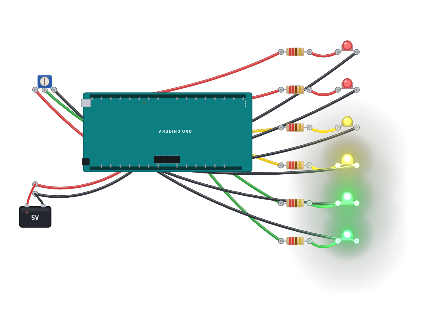
A VU-meter on the bench: the ATmega328P reads the trim pot with its real 10-bit ADC and lights a six-LED bar on D8-D13, green through red, one LED per ~160 counts. Click the pot and drag its Position slider in the Inspector to sweep the bar up and down; the raw reading prints over serial. The Code tab holds the same meter as an editable Arduino sketch.
How it works
A VU-meter in miniature, driven by a real ADC. The potentiometer's wiper divides 5 V, A0 samples it with the ATmega's genuine 10-bit converter (0–1023), and the sketch lights one LED per ~160 counts across the six-LED bar: green, green, yellow, yellow, red, red. Every 200 ms it prints the raw reading over serial, so you can watch the number and the bar move together as you drag the pot.
What's on the bench
- 6× LED
- 6× Resistor
- Arduino Uno R3
- Battery
- Trim Pot
How it's wired
- Battery · pos→Arduino Uno R3 · 5v
- Battery · neg→Arduino Uno R3 · gnd
- Trim Pot · a→Arduino Uno R3 · 5v
- Trim Pot · b→Arduino Uno R3 · gnd2
- Trim Pot · wiper→Arduino Uno R3 · a0
- Arduino Uno R3 · d8→Resistor · a
- Resistor · b→LED · a
- LED · k→Arduino Uno R3 · gnd2
- Arduino Uno R3 · d9→Resistor · a
- Resistor · b→LED · a
- LED · k→Arduino Uno R3 · gnd2
- Arduino Uno R3 · d10→Resistor · a
- Resistor · b→LED · a
- LED · k→Arduino Uno R3 · gnd2
- Arduino Uno R3 · d11→Resistor · a
- Resistor · b→LED · a
…and 7 more connections — open it in the simulator to see every wire.
The code
This Arduino C++ sketch lives in the Code tab; sign in and press Compile & upload to build real firmware for the emulated board.
// The same level meter as an Arduino sketch. Edit it, then Compile &
// upload (sign-in needed): the server builds real AVR firmware.
const int POT = A0;
const int LEDS[6] = {8, 9, 10, 11, 12, 13};  // green -> red

void setup() {
  for (int i = 0; i < 6; i++) pinMode(LEDS[i], OUTPUT);
  Serial.begin(9600);
}

void loop() {
  int v = analogRead(POT);        // 0..1023 from the real ADC
  int level = min(6, v / 160);    // one LED per ~160 counts
  for (int i = 0; i < 6; i++) digitalWrite(LEDS[i], i < level);
  Serial.print("A0 ");
  Serial.println(v);
  delay(200);
}
Try this
- Select the pot and drag its Position slider: the bar climbs and falls with the wiper.
- Open the Serial panel: 'A0 512' at half travel is the ratiometric ADC doing real math.
- Park the pot just below an LED’s threshold and nudge it one count at a time.
- Edit the sketch to light the bar top-down instead, then Compile & upload.