Example project · Builds & projects
Launch console (Mega 2560)
A mission-control panel that needs the Arduino Mega 2560’s ~36 spare GPIO — physically impossible on an Uno. Real compiled Arduino firmware drives a 16×2 LCD, a multiplexed 4-digit countdown display, an 8-LED status bank and a siren. The console stands by until you type 1234 on the keypad — then it narrates a T-minus-10 launch sequence over serial. Twist the fuel-mix pot (read on A8, one of the Mega’s extra ADC channels), and hit the red button to ABORT — wired to d2, which is interrupt INT4 on this chip.
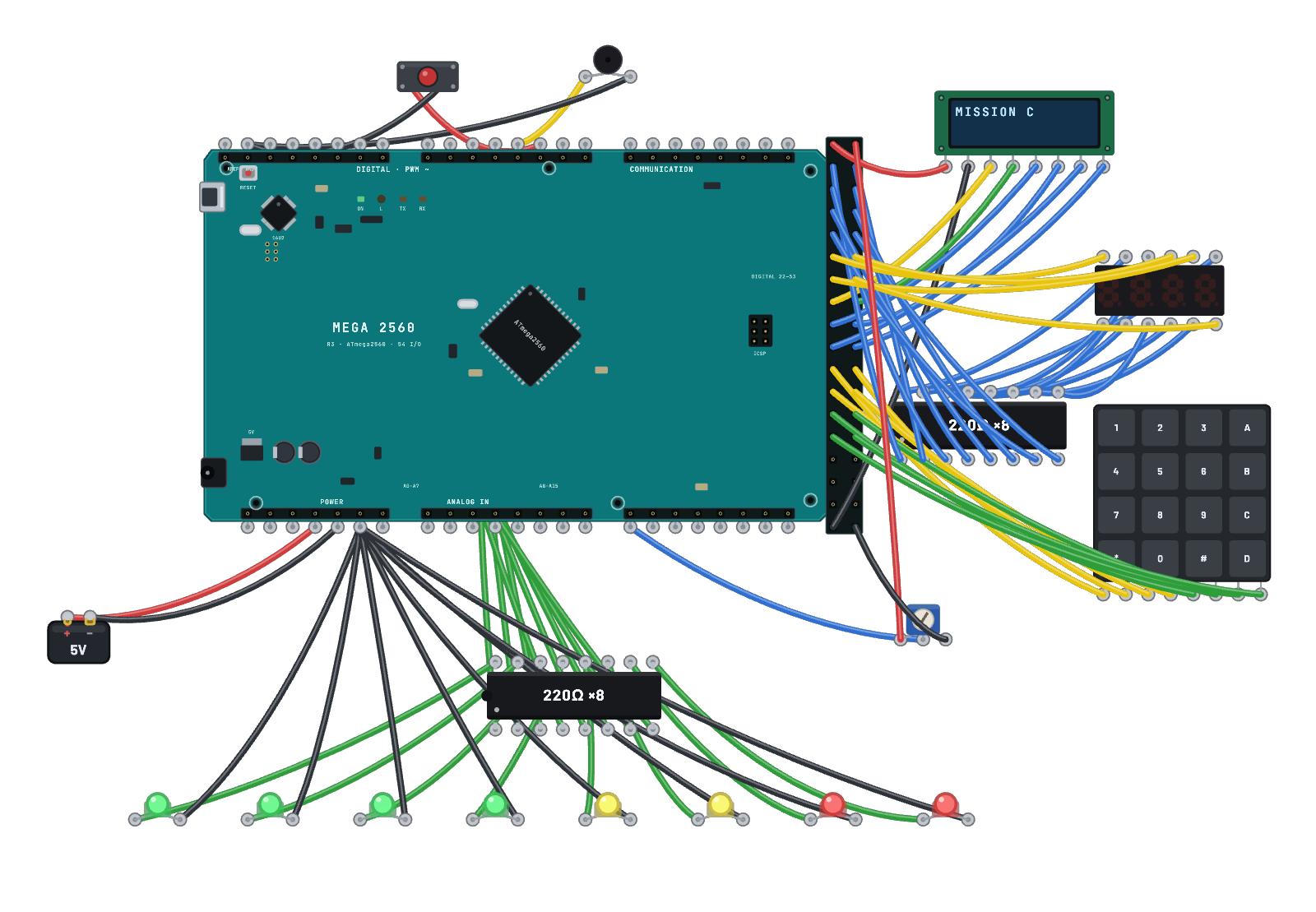
What's on the bench
- 8× LED
- 2× Resistor array ×8
- 7-Segment (4 digits)
- Arduino Mega 2560
- Battery
- Button
- Buzzer
- Keypad 4×4
- LCD 16×2
- Trim Pot
How it's wired
- Battery · pos→Arduino Mega 2560 · 5v
- Battery · neg→Arduino Mega 2560 · gnd
- LCD 16×2 · vcc→Arduino Mega 2560 · 5v2
- LCD 16×2 · gnd→Arduino Mega 2560 · gnd4
- LCD 16×2 · rs→Arduino Mega 2560 · d34
- LCD 16×2 · e→Arduino Mega 2560 · d35
- LCD 16×2 · d4→Arduino Mega 2560 · d36
- LCD 16×2 · d5→Arduino Mega 2560 · d37
- LCD 16×2 · d6→Arduino Mega 2560 · d38
- LCD 16×2 · d7→Arduino Mega 2560 · d39
- Keypad 4×4 · r0→Arduino Mega 2560 · d40
- Keypad 4×4 · r1→Arduino Mega 2560 · d41
- Keypad 4×4 · r2→Arduino Mega 2560 · d42
- Keypad 4×4 · r3→Arduino Mega 2560 · d43
- Keypad 4×4 · c0→Arduino Mega 2560 · d44
- Keypad 4×4 · c1→Arduino Mega 2560 · d45
…and 53 more connections — open it in the simulator to see every wire.
The code
This Arduino C++ sketch lives in the Code tab; sign in and press Compile & upload to build real firmware for the emulated board.
// ============================================================
// LAUNCH CONSOLE — an Arduino Mega 2560 mission-control panel.
//
// This panel is physically impossible on an Uno: it uses ~36 GPIO
// across five peripherals, an 8-LED status bank, an interrupt
// abort line and a 16-channel-ADC fuel gauge:
//
//   16x2 LCD (4-bit)   rs=34 en=35 d4..d7=36..39   (double-row header)
//   4x4 keypad         rows 40-43, cols 44-47      (arm code: 1234)
//   4-digit 7-segment  segments a..g,dp = 22..29 = the FULL PORTA,
//                      commons 30..33 = PC7..PC4 — whole-port writes
//                      keep the multiplex one bus event per strobe
//                      (shared segment lines — firmware multiplexes)
//   8 status LEDs      pins 5..12
//   piezo siren        pin 3 (tone())
//   ABORT button       pin 2 — INT4 on the 2560, attachInterrupt()
//   fuel-mix pot       A8 — channel 8, reached through ADCSRB.MUX5
//
// The console stands by until someone enters the arm code — 1234 on
// the keypad — then runs the narrated T-minus-10 launch sequence.
// The red button aborts through the external-interrupt path at any
// instant during the countdown.
// ============================================================

#include <avr/sleep.h>

// ----- pin map ------------------------------------------------
const uint8_t LCD_RS = 34, LCD_EN = 35;
const uint8_t LCD_D[4] = {36, 37, 38, 39};
const uint8_t KP_ROW[4] = {40, 41, 42, 43};
const uint8_t KP_COL[4] = {44, 45, 46, 47};
// 5641AS-style module: segment lines shared by all digits. Segments sit
// on d22..d29 = PA0..PA7 and the commons on d30..d33 = PC7..PC4, so the
// strobe is three whole-port writes instead of 13 digitalWrite events.
const uint8_t SEG[8] = {22, 23, 24, 25, 26, 27, 28, 29}; // a b c d e f g dp
const uint8_t DIG[4] = {30, 31, 32, 33};                 // common cathodes
const uint8_t LEDS[8] = {5, 6, 7, 8, 9, 10, 11, 12};
const uint8_t BUZZER = 3;
const uint8_t ABORT_BTN = 2; // INT4 (PE4) — EICRB territory

// ----- tiny HD44780 driver (4-bit, write-only) ----------------
// The core ships no LCD library; this is the classic init dance.
static void lcdPulse() {
  // Generous strobes: hold E 60 us high / 120 us low so both edges stay
  // visible to the simulator's mixed-signal sampling even when the
  // adaptive timestep has grown (real modules are happy with slow edges).
  digitalWrite(LCD_EN, HIGH);
  delayMicroseconds(60);
  digitalWrite(LCD_EN, LOW);
  delayMicroseconds(120);
}
static void lcdNibble(uint8_t v) {
  for (uint8_t i = 0; i < 4; i++) digitalWrite(LCD_D[i], (v >> i) & 1);
  lcdPulse();
}
static void lcdCmd(uint8_t v) {
  digitalWrite(LCD_RS, LOW);
  lcdNibble(v >> 4);
  lcdNibble(v & 0x0F);
  delayMicroseconds(100);
}
static void lcdData(uint8_t v) {
  digitalWrite(LCD_RS, HIGH);
  lcdNibble(v >> 4);
  lcdNibble(v & 0x0F);
  delayMicroseconds(100);
}
static void lcdInit() {
  pinMode(LCD_RS, OUTPUT);
  pinMode(LCD_EN, OUTPUT);
  for (uint8_t i = 0; i < 4; i++) pinMode(LCD_D[i], OUTPUT);
  delay(20);
  digitalWrite(LCD_RS, LOW);
  lcdNibble(0x3); delay(5);
  lcdNibble(0x3); delay(5);
  lcdNibble(0x3); delay(2);
  lcdNibble(0x2); delay(2);   // 4-bit mode
  lcdCmd(0x28);               // 2 lines, 5x8
  lcdCmd(0x0C);               // display on, no cursor
  lcdCmd(0x06);               // entry: increment
  lcdCmd(0x01); delay(2);     // clear
}
static void lcdLine(uint8_t row, const char* s) {
  lcdCmd(row ? 0xC0 : 0x80);
  bool ended = false;   // stop at NUL, pad with spaces (never read past it)
  for (uint8_t i = 0; i < 16; i++) {
    if (!ended && s[i] == 0) ended = true;
    lcdData(ended ? ' ' : s[i]);
  }
}

// ----- 7-segment multiplex ------------------------------------
// Glyphs as a..g bit sets. Index 10 = '-', 11 = blank.
const uint8_t GLYPH[12] = {
  0b0111111, 0b0000110, 0b1011011, 0b1001111, 0b1100110, 0b1101101,
  0b1111101, 0b0000111, 0b1111111, 0b1101111, 0b1000000, 0b0000000,
};
uint8_t shown[4] = {11, 11, 11, 11};

// Render one digit per call, round-robin, holding it ~3.5 ms — a ~70 Hz
// refresh the POV average reads as steady digits, at a pin-event rate
// the simulator paces comfortably (every toggle is an analog event).
// Idle-sleep hold: park the core in SLEEP_MODE_IDLE and let the timer0
// tick (and any serial/tone interrupt) wake it, until ~ms elapsed. Good
// embedded hygiene on real hardware — and the emulator's idle skip can
// credit slept cycles exactly, so the whole console paces at real time.
static void holdIdle(unsigned long ms) {
  const unsigned long start = millis();
  set_sleep_mode(SLEEP_MODE_IDLE);
  while (millis() - start < ms) sleep_mode();
}

static void displayTick() {
  static uint8_t which = 0;
  // Two back-to-back port writes: segments, then ONE common write that
  // releases the old digit and grabs the new in the same instruction.
  // Every pin edge is an analog event to the simulator, and the ~3-cycle
  // ghost of the new glyph on the old digit is far below anything the
  // eye (or the POV average) can see — real display drivers do the same.
  const uint8_t commons = (PORTC | 0xF0) & (uint8_t)~(0x80 >> which);
  PORTA = GLYPH[shown[which]];   // segments a..g on PA0..PA6 (dp clear)
  PORTC = commons;               // old digit off + new digit on, one write
  holdIdle(4);                   // ~62 Hz refresh, mostly asleep
  which = (which + 1) & 3;
}
static void showNumber(int n) { // right-aligned, blank-padded
  for (int8_t d = 3; d >= 0; d--) {
    if (n > 0 || d == 3) { shown[d] = n % 10; n /= 10; }
    else shown[d] = 11;
  }
}
static void showDashes() { shown[0] = shown[1] = shown[2] = shown[3] = 10; }

// ----- keypad -------------------------------------------------
const char KP_KEYS[17] = "123A456B789C*0#D";
static char keypadScan() {
  // Idle trick: ALL rows rest low, so any pressed key pulls its column
  // low with zero pin motion — an idle scan moves nothing (kind to real
  // silicon and to the simulator, where every pin edge is an analog
  // event). Only while something is down does the one-row-at-a-time
  // scan identify it. Throttled to ~40 scans/s.
  static unsigned long lastScan = 0;
  static char held = 0; // edge-detect: report a key once per press
  if (millis() - lastScan < 25) return 0;
  lastScan = millis();
  bool any = false;
  for (uint8_t c = 0; c < 4; c++) {
    if (digitalRead(KP_COL[c]) == LOW) any = true;
  }
  if (!any) {
    held = 0;
    return 0;
  }
  char hit = 0;
  for (uint8_t r = 0; r < 4; r++) {
    // Isolate row r: raise the other three, leave r low.
    for (uint8_t i = 0; i < 4; i++) digitalWrite(KP_ROW[i], i == r ? LOW : HIGH);
    delayMicroseconds(50); // let the levels settle before sampling
    for (uint8_t c = 0; c < 4; c++) {
      if (digitalRead(KP_COL[c]) == LOW) hit = KP_KEYS[r * 4 + c];
    }
  }
  for (uint8_t i = 0; i < 4; i++) digitalWrite(KP_ROW[i], LOW); // back to rest
  if (hit == held) return 0;
  held = hit;
  return hit;
}

// ----- abort interrupt ----------------------------------------
volatile bool abortRequested = false;
void onAbort() { abortRequested = true; } // INT4 fires this

// ----- state machine ------------------------------------------
enum State { STANDBY, COUNTDOWN, LIFTOFF, ABORTED };
State state = STANDBY;
unsigned long stateSince = 0, lastSecond = 0;
int tMinus = 10;
char code[5] = "";
uint8_t codeLen = 0;
int fuelPct = 0;

static void ledBank(uint8_t lit) {
  static uint8_t last = 0xFF;
  if (lit == last) return; // redundant writes are wasted work
  last = lit;
  for (uint8_t i = 0; i < 8; i++) digitalWrite(LEDS[i], i < lit);
}

static void enterStandby() {
  state = STANDBY;
  stateSince = millis();
  codeLen = 0;
  code[0] = 0;
  lcdLine(0, "MISSION CONTROL");
  lcdLine(1, "ARM CODE: 1234");
  Serial.println(F("Standing by - enter 1234 on the keypad to launch"));
}

static void startCountdown() {
  state = COUNTDOWN;
  stateSince = millis();
  lastSecond = millis();
  tMinus = 10;
  lcdLine(0, "SEQUENCE ARMED");
  lcdLine(1, "RED BTN = ABORT");
  Serial.println(F("Code accepted - sequence ARMED"));
  Serial.print(F("T-minus "));
  Serial.println(tMinus);
  showNumber(tMinus);
  ledBank(1);
  tone(BUZZER, 880, 120);
}

void setup() {
  Serial.begin(9600);
  lcdInit();
  for (uint8_t i = 0; i < 4; i++) {
    pinMode(KP_ROW[i], OUTPUT);
    digitalWrite(KP_ROW[i], LOW); // rows rest low (see keypadScan)
    pinMode(KP_COL[i], INPUT_PULLUP);
  }
  for (uint8_t i = 0; i < 8; i++) pinMode(SEG[i], OUTPUT);
  for (uint8_t i = 0; i < 4; i++) { pinMode(DIG[i], OUTPUT); digitalWrite(DIG[i], HIGH); }
  for (uint8_t i = 0; i < 8; i++) pinMode(LEDS[i], OUTPUT);
  pinMode(ABORT_BTN, INPUT_PULLUP);
  // d2 is INT4 on the 2560 — the EICRB bank, not the Uno's INT0.
  attachInterrupt(digitalPinToInterrupt(ABORT_BTN), onAbort, FALLING);
  fuelPct = map(analogRead(A8), 0, 1023, 0, 100); // MUX5 channel
  Serial.println(F("LAUNCH CONSOLE ONLINE"));
  Serial.print(F("Fuel mix: "));
  Serial.print(fuelPct);
  Serial.println(F("%"));
  enterStandby();
}

void loop() {
  displayTick(); // ~1.8 ms per pass keeps every digit lit via POV

  const unsigned long now = millis();

  // The abort line is live in every state that can be un-idled.
  if (abortRequested) {
    abortRequested = false;
    if (state == COUNTDOWN) {
      state = ABORTED;
      stateSince = now;
      showDashes();
      lcdLine(0, "ABORT  ABORT");
      lcdLine(1, "PAD SAFED");
      Serial.println(F("ABORT! Safing the pad"));
      tone(BUZZER, 220, 600);
    }
  }

  switch (state) {
    case STANDBY: {
      showNumber(fuelPct);
      // slow chase on the status bank while standing by
      ledBank(((now / 250) % 9));
      const char k = keypadScan();
      if (k >= '0' && k <= '9' && codeLen < 4) {
        code[codeLen++] = k;
        code[codeLen] = 0;
        char line[17];
        for (uint8_t i = 0; i < 16; i++) line[i] = ' ';
        line[16] = 0;
        memcpy(line, "CODE: ", 6);
        memcpy(line + 6, code, codeLen);
        lcdLine(1, line);
        if (codeLen == 4) {
          if (strcmp(code, "1234") == 0) {
            startCountdown();
          } else {
            Serial.println(F("Code rejected"));
            lcdLine(1, "BAD CODE");
            codeLen = 0;
            code[0] = 0;
          }
        }
      } else if (k == '*') {
        codeLen = 0;
        code[0] = 0;
        lcdLine(1, "ARM CODE: 1234");
      }
      break;
    }
    case COUNTDOWN: {
      if (now - lastSecond >= 1000) {
        lastSecond += 1000;
        tMinus--;
        if (tMinus <= 0) {
          state = LIFTOFF;
          stateSince = now;
          showNumber(0);
          ledBank(8);
          lcdLine(0, "LIFTOFF");
          lcdLine(1, "GODSPEED");
          Serial.println(F("LIFTOFF! We have liftoff"));
          tone(BUZZER, 1760, 900);
        } else {
          Serial.print(F("T-minus "));
          Serial.println(tMinus);
          showNumber(tMinus);
          ledBank(min(10 - tMinus, 8)); // bank fills as T falls
          tone(BUZZER, 880, 120);
        }
      }
      break;
    }
    case LIFTOFF: {
      ledBank(((now / 120) & 1) ? 8 : 6); // engine flicker
      if (now - stateSince > 3000) enterStandby();
      break;
    }
    case ABORTED: {
      ledBank(((now / 200) & 1) ? 8 : 0); // alarm flash
      if (now - stateSince > 3000) enterStandby();
      break;
    }
  }
}