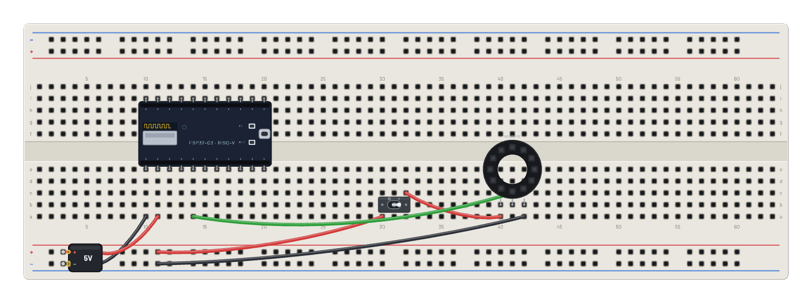
Componentes del montaje
- Anillo NeoPixel ×12 (NeoPixel ring ×12)
- ESP32-C3
- Interruptor de palanca (Toggle switch)
Cómo está conectado
- orificio a10→orificio B-5
- orificio a11→orificio B+5
- orificio B+9→orificio a30
- orificio c32→orificio a40
- orificio a42→orificio B-9
- orificio a14→orificio c41
- ESP32-C3 · gnd→orificio e10
- ESP32-C3 · vin→orificio e11
- ESP32-C3 · g2→orificio e14
El código
Este script de MicroPython se ejecuta en la placa emulada en cada arranque; edítalo en Code.
# Rainbow chase on the ring. The toggle switch gates the ring's 5 V pin:
# flick it off and the pixels go dark instantly; flick it back on and the
# next frame repaints them. The C3 keeps streaming frames throughout.
import machine, neopixel, time

RAINBOW = [
    (255, 0, 0), (255, 96, 0), (255, 200, 0), (96, 255, 0),
    (0, 255, 60), (0, 255, 200), (0, 160, 255), (0, 40, 255),
    (90, 0, 255), (200, 0, 255), (255, 0, 160), (255, 0, 60),
]
np = neopixel.NeoPixel(machine.Pin(2), 12)
for step in range(4000):
    for i in range(12):
        np[i] = RAINBOW[(i + step) % 12]
    np.write()
    time.sleep_ms(120)
print('ring demo done')