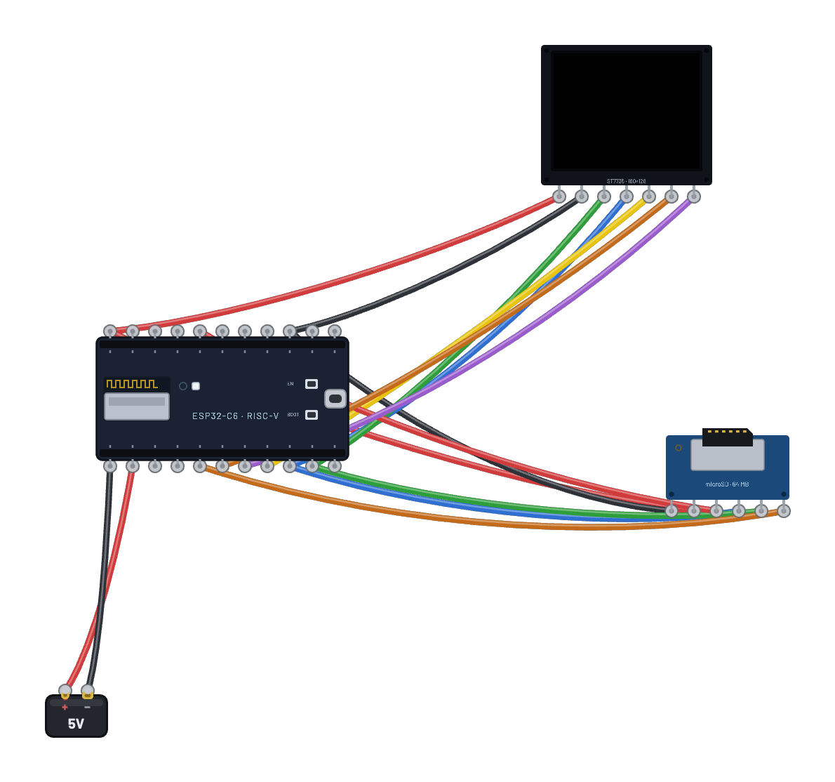
Cómo funciona
Dos periféricos SPI comparten bus: microSD y ST7735 en SPI por hardware del C6 (SCK=6, MOSI=7, MISO=2: pines fijos de `machine.SPI(1)`); las líneas de selección deciden quién escucha. El firmware no tiene módulo `sdcard`: el script ES el controlador. CMD0 pone la tarjeta en modo SPI, CMD8/ACMD41 negocian SDHC y las lecturas usan CMD18 multibloque con parada CMD12 (las mismas ~40 líneas de partida de un proyecto SD SPI real). `vfs.VfsFat` monta FAT16 de solo lectura; cada foto es un `.565` sin comprimir (cabecera de 4 bytes de ancho/alto y píxeles RGB565 big-endian). Mostrarla es abrir, leer bloques de 4 KB y escribir en la ventana RAMWR ST7735. No hay decodificación. Las fotos vienen del documento del circuito: el Inspector convierte imágenes a `.565` en el navegador y guarda referencias; el motor escribe archivos FAT16 reales al arrancar.
Componentes del montaje
- ESP32-C6
- Tarjeta microSD (microSD card)
- TFT 1.8″ 160×128 (ST7735)
Cómo está conectado
- ESP32-C6 · 3v3→TFT 1.8″ 160×128 (ST7735) · vcc
- ESP32-C6 · gnd2→TFT 1.8″ 160×128 (ST7735) · gnd
- ESP32-C6 · 3v3→Tarjeta microSD (microSD card) · vcc
- ESP32-C6 · gnd2→Tarjeta microSD (microSD card) · gnd
- ESP32-C6 · g6→TFT 1.8″ 160×128 (ST7735) · clk
- ESP32-C6 · g6→Tarjeta microSD (microSD card) · sck
- ESP32-C6 · g7→TFT 1.8″ 160×128 (ST7735) · din
- ESP32-C6 · g7→Tarjeta microSD (microSD card) · mosi
- ESP32-C6 · g2→Tarjeta microSD (microSD card) · miso
- ESP32-C6 · g5→TFT 1.8″ 160×128 (ST7735) · cs
- ESP32-C6 · g20→Tarjeta microSD (microSD card) · cs
- ESP32-C6 · g3→TFT 1.8″ 160×128 (ST7735) · dc
- ESP32-C6 · g4→TFT 1.8″ 160×128 (ST7735) · rst
El código
Este script de MicroPython se ejecuta en la placa emulada en cada arranque; edítalo en Code.
# microSD photo frame - the photos live on the card, streamed
# straight to the TFT over the shared SPI bus. Select the card and
# open the Inspector's Card contents panel to swap in your own
# images (they convert to raw .565 on upload).
# There is no sdcard module in the firmware - this IS the driver,
# the same ~40 lines every SPI-mode SD project starts from.
from machine import Pin, SPI
import os, vfs, time

spi = SPI(1, baudrate=20000000)  # C6 hardware SPI: sck=6, mosi=7, miso=2
scs = Pin(20, Pin.OUT, value=1)  # SD chip-select
tcs = Pin(5, Pin.OUT, value=1)   # TFT chip-select
dc = Pin(3, Pin.OUT)
rst = Pin(4, Pin.OUT)

class SD:
    def __init__(self):
        spi.write(b'\xff' * 10)            # >=74 idle clocks, CS high
        assert self._cmd(0, 0, 0x95) == 1   # CMD0: go idle
        self._cmd(8, 0x1AA, 0x87, 4)        # CMD8: voltage check + echo
        while True:                         # CMD55+ACMD41 until ready
            self._cmd(55, 0, 1)
            if self._cmd(41, 0x40000000, 1) == 0:
                break
        self._cmd(58, 0, 1, 4)              # CMD58: OCR (SDHC addressing)
    def _cmd(self, c, a, crc, extra=0):
        scs(0)
        spi.write(bytes([0x40 | c, a >> 24 & 0xFF, a >> 16 & 0xFF, a >> 8 & 0xFF, a & 0xFF, crc]))
        r = 0xFF
        for _ in range(20):
            r = spi.read(1, 0xFF)[0]
            if not r & 0x80:
                break
        if extra:
            spi.read(extra, 0xFF)
        scs(1); spi.write(b'\xff')
        return r
    def readblocks(self, n, buf):
        mv = memoryview(buf)
        scs(0)                              # CMD18: multi-block read
        spi.write(bytes([0x52, n >> 24 & 0xFF, n >> 16 & 0xFF, n >> 8 & 0xFF, n & 0xFF, 1]))
        while spi.read(1, 0xFF)[0] != 0:    # R1
            pass
        for i in range(len(buf) // 512):
            while spi.read(1, 0xFF)[0] != 0xFE:  # data token
                pass
            spi.readinto(mv[512 * i:512 * (i + 1)], 0xFF)
            spi.read(2, 0xFF)               # CRC
        spi.write(bytes([0x4C, 0, 0, 0, 0, 1]))  # CMD12: stop
        spi.read(8, 0xFF)
        scs(1); spi.write(b'\xff')
    def ioctl(self, op, arg):
        if op == 4: return 131072           # sector count (64 MiB)
        if op == 5: return 512              # bytes per sector

vfs.mount(vfs.VfsFat(SD()), '/sd', readonly=True)

def wr(c, d=None):
    tcs(0); dc(0); spi.write(bytes([c]))
    if d is not None:
        dc(1); spi.write(bytes(d))
    tcs(1)

rst(0); time.sleep_ms(20); rst(1); time.sleep_ms(50)
wr(0x01); time.sleep_ms(120)   # SWRESET
wr(0x11); time.sleep_ms(120)   # SLPOUT
wr(0x3A, [0x05])               # COLMOD 16-bit RGB565
wr(0x29)                       # DISPON

buf = bytearray(4096)
mv = memoryview(buf)

def blit(f, w, h):
    wr(0x2A, [0, 0, 0, w - 1])  # CASET
    wr(0x2B, [0, 0, 0, h - 1])  # RASET
    tcs(0); dc(0); spi.write(bytes([0x2C])); dc(1)  # RAMWR, then stream
    left = w * h * 2
    while left:
        n = f.readinto(mv[:min(left, len(buf))])
        if not n:
            break
        spi.write(mv[:n])
        left -= n
    tcs(1)

# Photos are .565 with a 4-byte header (w, h); videos (the Inspector's
# "Add video..." output) carry an 8-byte header (w, h, fps, frames) and
# play PACED at their own frame rate. Size tells them apart.
media = sorted(n for n in os.listdir('/sd') if n.endswith('.565'))
print('card:', media)
while True:
    for name in media:
        size = os.stat('/sd/' + name)[6]
        f = open('/sd/' + name, 'rb')
        hdr = f.read(4)
        w = hdr[0] | hdr[1] << 8
        h = hdr[2] | hdr[3] << 8
        if size == 4 + w * h * 2:   # single photo: show for 3 s
            blit(f, w, h)
            f.close()
            print('PHOTO', name)
            time.sleep(3)
            continue
        hdr = f.read(4)             # video: fps + frame count
        fps = hdr[0] | hdr[1] << 8
        nf = hdr[2] | hdr[3] << 8
        print('VIDEO', name, w, 'x', h, '@', fps, 'fps,', nf, 'frames')
        budget = max(1, 1000 // max(1, fps))
        t0 = time.ticks_ms()
        nxt = time.ticks_add(t0, budget)
        for _ in range(nf):
            blit(f, w, h)
            d = time.ticks_diff(nxt, time.ticks_ms())
            if d > 0:
                time.sleep_ms(d)
            nxt = time.ticks_add(nxt, budget)
        f.close()
        ms = time.ticks_diff(time.ticks_ms(), t0)
        print('PLAYED', name, nf * 1000 // max(1, ms), 'fps achieved')
Prueba esto
- Selecciona microSD y abre Card contents en el Inspector. Aparecen tres fotos. Añade una imagen propia; la placa se reinicia con ella en la tarjeta.
- Observa el monitor serial: una línea `PHOTO <name>` por foto mostrada.
- Cambia `time.sleep(3)` en Code para acelerar la presentación o cambia el orden.
- Abre Logic analyzer al cargar una foto para ver lecturas CMD18 intercaladas con ráfagas RAMWR en el bus compartido.